


User’s Manual
IBM PowerPC 750GX and 750GL RISC Microprocessor
PowerPC 750GX Overview
Page 40 of 377
gx_01.fm.(1.2)
March 27,2006
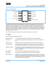
1.2.9 Clocking
The 750GX requires a single system clock input, SYSCLK, that represents the bus interface frequency. Inter-
nally, the processor uses a phase-locked loop (PLL) circuit to generate a master core clock that is frequency-
multiplied and phase-locked to the SYSCLK input. This core frequency is used to operate the internal
circuitry.
The PLL is configured by the PLL_CFG[0:4] signals, which select the multiplier that the PLL uses to multiply
the SYSCLK frequency up to the internal core frequency. In addition, the 750GX has two PLL_RNG bits that
set the proper operation frequency range. The feedback in the PLL guarantees that the processor clock is
phase locked to the bus clock, regardless of process variations, temperature changes, or parasitic capaci-
tances.
The PLL also ensures a 50% duty cycle for the processor clock.
The 750GX supports various processor-to-bus clock frequency ratios, although not all ratios are available for
all frequencies. Configuration of the processor/bus clock ratios is displayed through a 750GX-specific
register, HID1. For information about supported clock frequencies, see the PowerPC 750GX Datasheet.
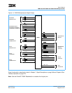
1.3 750GX Microprocessor Implementation
The PowerPC Architecture is derived from the Performance Optimized with Enhanced RISC (POWER™)
architecture. The PowerPC Architecture shares the benefits of the POWER architecture optimized for single-
chip implementations. The PowerPC Architecture design facilitates parallel instruction execution, and is scal-
able to take advantage of future technological gains.
The remainder of this chapter describes the PowerPC Architecture in general, and specific details about the
implementation of 750GX as a low-power, 32-bit member of the PowerPC processor family. The structure of
the remainder of this chapter reflects the organization of the user’s manual; each section provides an over-
view of the corresponding chapter. The following sections summarize the features of the 750GX, distin-
guishing those that are defined by the architecture from those that are unique to the 750GX implementation.
Registers and
programming model
Section 1.4, PowerPC Registers and Programming Model, on page 42 describes
the registers for the operating environment architecture common among PowerPC
processors and describes the programming model. It also describes the registers
that are unique to the 750GX. The information in this section is described more fully
in Chapter 2, Programming Model, on page 57.
Instruction set and
addressing modes
Section 1.5, Instruction Set, on page 45 describes the PowerPC instruction set and
addressing modes for the PowerPC operating environment architecture, defines
the PowerPC instructions implemented in the 750GX, and describes new instruc-
tion set extensions to improve the performance of single-precision floating-point
operations and the capability of data transfer. The information in this section is
described more fully in Section 2.3, Instruction Set Summary, on page 86.
Cache implementation Section 1.6, On-Chip Cache Implementation, on page 47 describes the cache
model that is defined generally for PowerPC processors by the virtual environment
architecture. It also provides specific details about the 750GX L2 cache implemen-
tation. The information in this section is described more fully in Chapter 3, Instruc-
tion-Cache and Data-Cache Operation, on page 121.