


User’s Manual
IBM PowerPC 750GX and 750GL RISC Microprocessor
gx_02.fm.(1.2)
March 27, 2006
Programming Model
Page 79 of 377
2.1.4.2 Thermal-Management Register 3 (THRM3)
The THRM3 register is used to enable the thermal assist unit and to control the timing of the output sample
comparison. The thermal assist logic manages the thermal-management interrupt generation and time-multi-
plexed comparisons in dual-threshold mode, as well as other control functions.
The THRM registers can be accessed with the mtspr and mfspr instructions using the following SPR
numbers:
• THRM1 is SPR 1020
• THRM2 is SPR 1021
• THRM3 is SPR 1022
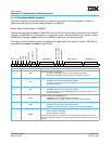
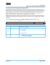
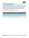
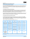
Table 2-3. Valid THRM1/THRM2 Bit Settings
TIN
1
TIV
1
TID TIE V Description
xxxx0Invalid entry. The threshold in the SPR is not used for comparison.
x x x 0 1 Disable thermal-management interrupt assertion.
xx0x1
Set TIN and assert thermal-management interrupt if TIE = 1 and the junction temper-
ature exceeds the threshold. If TIE = 0, then no interrupt will be taken when the
threshold is achieved.
xx1x1
Set TIN and assert thermal-management interrupt if TIE = 1 and the junction temper-
ature is less than the threshold.
x 0 x x 1 The state of the TIN bit is not valid.
010x1
The junction temperature is less than the threshold and as a result the thermal-man-
agement interrupt is not generated for TIE = 1.
110x1
The junction temperature is greater than the threshold and as a result the thermal-
management interrupt is generated if TIE = 1.
011x1
The junction temperature is greater than the threshold and as a result the thermal-
management interrupt is not generated for TIE = 1.
111x1
The junction temperature is less than the threshold and as a result the thermal-man-
agement interrupt is generated if TIE = 1
1. TIN and TIV are read-only status bits.
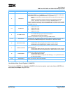
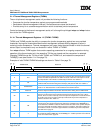
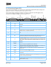
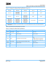
Reserved SITV E
012345678910111213141516171819202122232425262728293031
Bits Field Name Description
0:14 Reserved Reserved for future use. System software should clear these bits when writing to THRM3.
15:30 SITV
Sample interval timer value. Number of elapsed processor clock cycles before a junction
temperature versus threshold comparison result is sampled to set the TIN bit and gener-
ate an interrupt. This is necessary due to the thermal sensor, the digital-to-analog con-
verter (DAC), and because the analog comparator settling time is greater than the
processor cycle time. The value should be configured to allow a sampling interval of 20
microseconds.
31 E Enables the thermal sensor compare operation if either THRM1[V] or THRM2[V] is set.