


User’s Manual
IBM PowerPC 750GX and 750GL RISC Microprocessor
gx_02.fm.(1.2)
March 27, 2006
Programming Model
Page 61 of 377
– Memory-management registers
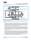
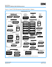
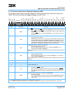
• Block-Address Translation (BAT) Registers. The PowerPC OEA includes an array of Block
Address Translation Registers that can be used to specify eight blocks of instruction space and
eight blocks of data space. The BAT registers are implemented in pairs—eight pairs of instruction
BATs (IBAT0U–IBAT7U and IBAT0L–IBAT7L) and eight pairs of data BATs (DBAT0U–DBAT7U
and DBAT0L–DBAT7L). Figure 2-1, PowerPC 750GX Microprocessor Programming Model—
Registers lists the SPR numbers for the BAT registers. For more information, see “BAT Regis-
ters” in Chapter 2, “PowerPC Register Set” of the PowerPC Microprocessor Family: The Pro-
gramming Environments Manual. Because BAT upper and lower words are loaded separately,
software must ensure that BAT translations are correct during the time that both BAT entries are
being loaded.
The 750GX implements the G bit in the IBAT registers. However, attempting to execute code
from an IBAT area with G = 1 causes an instruction storage interrupt (ISI) exception. This com-
plies with the revision of the architecture described in the PowerPC Microprocessor Family: The
Programming Environments Manual.
• SDR1. The SDR1 register specifies the page table base address used in virtual-to-physical
address translation. See “SDR1” in Chapter 2, “PowerPC Register Set” of the PowerPC Micro-
processor Family: The Programming Environments Manual.”
• Segment Registers (SR). The PowerPC OEA defines sixteen 32-bit Segment Registers (SR0–
SR15). Note that the SRs are implemented on 32-bit implementations only. The fields in the Seg-
ment Register are interpreted differently depending on the value of bit 0. See “Segment Regis-
ters” in Chapter 2, “PowerPC Register Set” of the PowerPC Microprocessor Family: The
Programming Environments Manual for more information.
Note: The 750GX implements separate memory management units (MMUs) for instruction and
data. It associates the architecture-defined SRs with the data MMU (DMMU). It reflects the val-
ues of the SRs in separate, so-called ‘shadow’ Segment Registers in the instruction MMU
(IMMU).
– Exception-handling registers
• Data Address Register (DAR). After a data-storage interrupt (DSI) exception or an alignment
exception, DAR is set to the effective address (EA) generated by the instruction at fault. See
“Data Address Register (DAR)” in Chapter 2, “PowerPC Register Set” of the PowerPC Micropro-
cessor Family: The Programming Environments Manual for more information.
• SPRG0–SPRG3. The SPRG0–SPRG3 registers are provided for operating system use. See
“SPRG0–SPRG3” in Chapter 2, “PowerPC Register Set” of the PowerPC Microprocessor Family:
The Programming Environments Manual for more information.
• DSISR. The Data Storage Interrupt Status Register (DSISR) defines the cause of DSI and align-
ment exceptions. See “DSISR” in Chapter 2, “PowerPC Register Set” of the PowerPC Micropro-
cessor Family: The Programming Environments Manual for more information.
• Machine Status Save/Restore Register 0 (SRR0). The SRR0 register is used to save the address
of the instruction at which execution continues when an rfi executes at the end of an exception
handler routine. See “Machine Status Save/Restore Register 0 (SRR0)” in Chapter 2, “PowerPC
Register Set” of the PowerPC Microprocessor Family: The Programming Environments Manual
for more information.
• Machine Status Save/Restore Register 1 (SRR1). The SRR1 is used to save machine status on
exceptions and to restore machine status when rfi executes. See “Machine Status Save/Restore