


User’s Manual
IBM PowerPC 750GX and 750GL RISC Microprocessor
gx_08.fm.(1.2)
March 27, 2006
Bus Interface Operation
Page 295 of 377
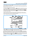
The basic coherency size of the bus is defined to be 32 bytes (corresponding to one cache line). Data trans-
fers that cross an aligned, 32-byte boundary either must present a new address onto the bus at that boundary
(for coherency consideration) or must operate as noncoherent data with respect to the 750GX. The 750GX
never generates a bus transaction with a transfer size of 5 bytes, 6 bytes, or 7 bytes.
Write-Through (WT
) Signal
The 750GX provides the WT
signal to indicate a write-through operation as determined by the WIM bit
settings during address translation by the MMU. The WT
signal is also asserted for burst writes due to the
execution of the dcbf and dcbst instructions, and snoop push operations. The WT
signal is deasserted for
accesses caused by the execution of the External Control Out Word Indexed (ecowx) instruction. During
read operations, the 750GX uses the WT
signal to indicate whether the transaction is an instruction fetch (WT
negated) or a data read operation (WT
asserted).
Cache Inhibit (CI
) Signal
The 750GX indicates the caching-inhibited status of a transaction (determined by the setting of the WIM bits
by the MMU) through the use of the CI
signal. The CI signal is asserted even if the L1 caches are disabled or
locked. This signal is also asserted for bus transactions caused by the execution of eciwx and ecowx instruc-
tions independent of the address translation.
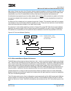
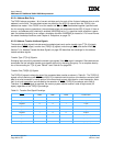
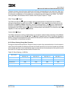
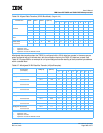
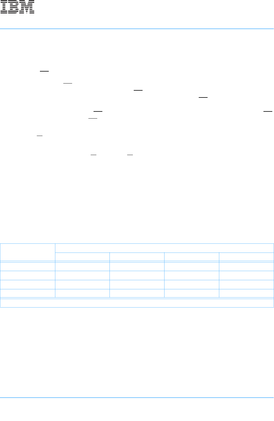
8.3.2.3 Burst Ordering During Data Transfers
During burst data-transfer operations, 32 bytes of data (one cache line) are transferred to or from the cache in
order. Burst write transfers are always performed zero double word first, but since burst reads are performed
critical double word first, a burst read transfer might not start with the first double word of the cache line, and
the cache-line fill might wrap around the end of the cache line.
Table 8-2. Burst Ordering—64-Bit Bus
Data Transfer
Double-Word Starting Address:
A[27–28] = 00 A[27–28] = 01 A[27–28] = 10 A[27–28] = 11
First data beat DW0 DW1 DW2 DW3
Second data beat DW1 DW2 DW3 DW0
Third data beat DW2 DW3 DW0 DW1
Fourth data beat DW3 DW0 DW1 DW2
Note: A[29–31] are always 0b000 for burst transfers by the 750GX.