


User’s Manual
IBM PowerPC 750GX and 750GL RISC Microprocessor
Bus Interface Operation
Page 280 of 377
gx_08.fm.(1.2)
March 27, 2006
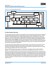
8.1 Bus Interface Overview
The bus interface prioritizes requests for bus operations from the instruction and data caches, and performs
bus operations in accordance with the protocol described in the PowerPC Microprocessor Family: The Bus
Interface for 32-Bit Microprocessors. It includes Address Register queues, prioritization logic, and a bus
control unit. The bus interface latches snoop addresses for snooping in the data cache and in the Address
Register queues, and for reservations controlled by the Load Word and Reserve Indexed (lwarx) and Store
Word Conditional Indexed (stwcx.) instructions, and maintains the touch load address for the cache. The
interface allows four levels of pipelining for load/store transactions. That is, with certain restrictions discussed
later, there can be four outstanding load/store transactions at any given time. Accesses are prioritized with
load operations preceding store operations.
Instructions are automatically fetched from the memory system into the instruction unit (a maximum of four
per cycle) where they are dispatched to the execution units at a peak rate of two instructions per clock.
Conversely, load-and-store instructions explicitly specify the movement of operands to and from the integer
and Floating Point Register files and the memory system.
When the 750GX encounters an instruction or data access, it calculates the logical address (effective
address in the architecture specification) and uses the low-order address bits to check for a hit in the L1
32-KB instruction and data caches. During cache lookup, the instruction and data memory management units
(MMUs) use the higher-order address bits to calculate the virtual address from which they calculate the phys-
ical address (real address in the architecture specification). The physical address bits are then compared with
the corresponding cache tag bits to determine if a cache hit occurred in the L1 instruction or data cache. If the
access misses in the corresponding cache, the physical address is used to access the L2 cache tags (if the
L2 cache is enabled). If no match is found in the L2 cache tags, the physical address is used to access
system memory.
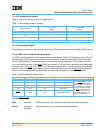
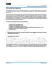
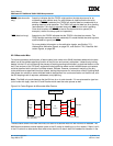
Figure 8-1. Bus Interface Address Buffers
Snoop
Control Address Address Data
L2 or System Bus
Instruction
Data Cache
Data Cache
Snoop
Reservation
Address
Data Cache
Castout/
Instruction
Data Cache
Load
Dat
a
L2
Castout
Cache
Cache
Load
Address
Address
Store
Address
Address Buffer
Bus
Interface
Unit
(BIU)
Control