


User’s Manual
IBM PowerPC 750GX and 750GL RISC Microprocessor
gx_01.fm.(1.2)
March 27,2006
PowerPC 750GX Overview
Page 41 of 377
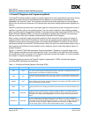
The PowerPC Architecture consists of the following layers, and adherence to the PowerPC Architecture can
be described in terms of which of the following levels of the architecture is implemented.
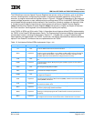
Exception mode Section 1.7, Exception Model, on page 48 describes the exception model of the
PowerPC operating environment architecture and the differences in the 750GX
exception model. The information in this section is described more fully in
Chapter 4, Exceptions, on page 151.
Memory management Section 1.8, Memory Management, on page 51 describes in general terms the
conventions for memory management among the PowerPC processors. This
section also describes the 750GX’s implementation of the 32-bit PowerPC
memory-management specification. The information in this section is described
more fully in Chapter 5, Memory Management, on page 179.
Instruction timing Section 1.9, Instruction Timing, on page 52 provides a general description of the
instruction timing provided by the superscalar, parallel execution supported by the
PowerPC Architecture and the 750GX. The information in this section is described
in more detail in Chapter 6, Instruction Timing, on page 209.
Power management Section 1.10, Power Management, on page 54 describes how power management
can be used to reduce power consumption when the processor, or portions of it,
are idle. The information in this section is described more fully in Chapter 10,
Power and Thermal Management, on page 335.
Thermal management Section 1.11, Thermal Management, on page 55 describes how the thermal-
management unit and its associated registers (THRM1–THRM4) and exception
processing can be used to manage system activity in a way that prevents
exceeding system and junction temperature thresholds. This is particularly useful in
high-performance portable systems, which cannot use the same cooling mecha-
nisms (such as fans) that control overheating in desktop systems. The information
in this section is described more fully in Chapter 10, Power and Thermal Manage-
ment, on page 335.
Performance monitor Section 1.12, Performance Monitor, on page 56 describes the performance-
monitor facility, which system designers can use to help bring up, debug, and opti-
mize software performance. The information in this section is described more fully
in Chapter 11, Performance Monitor and System Related Features, on page 349.
PowerPC user instruction
set architecture (UISA)
Defines the base user-level instruction set, user-level registers, data types,
floating-point exception model, memory models for a uniprocessor environment,
and programming model for a uniprocessor environment.
PowerPC virtual environ-
ment architecture (VEA)
Describes the memory model for a multiprocessor environment, defines cache-
control instructions, and describes other aspects of virtual environments. Imple-
mentations that conform to the VEA also adhere to the UISA, but might not neces-
sarily adhere to the OEA.
PowerPC operating
environment architecture
(OEA)
Defines the memory-management model, supervisor-level registers, synchroniza-
tion requirements, and the exception model. Implementations that conform to the
OEA also adhere to the UISA and the VEA.