


User’s Manual
IBM PowerPC 750GX and 750GL RISC Microprocessor
gx_06.fm.(1.2)
March 27, 2006
Instruction Timing
Page 233 of 377
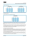
6.4.5 Load/Store Unit Execution Timing
The execution of most load-and-store instructions is pipelined. The LSU has two pipeline stages. The first is
for effective address calculation and MMU translation, and the second is for accessing data in the cache.
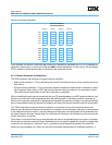
Load-and-store instructions have a 2-cycle latency and 1-cycle throughput. For instructions that store FPR
values (Store Floating-Point Double [stfd], Store Floating-Point Single [stfs], and their variations), the data to
be stored is prefetched from the source register during the first pipeline stage. In cases where this register is
updated that same cycle, the instruction will stall to get the correct data, resulting in one additional cycle of
latency.
If operands are misaligned, additional latency might be required either for an alignment exception to be taken
or for additional bus accesses. Load instructions that miss in the cache block require subsequent cache
accesses during the cache-line refill. Table 6-9 on page 244 gives load-and-store instruction execution laten-
cies.
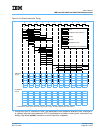
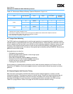
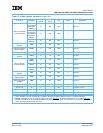
6.4.6 Effect of Operand Placement on Performance
The PowerPC virtual environment architecture (VEA) states that the placement (location and alignment) of
operands in memory might affect the relative performance of memory accesses, and in some cases affect it
significantly. The effects memory operand placement has on performance are shown in Table 6-2.
The best performance is guaranteed if memory operands are aligned on natural boundaries. For the best
performance across the widest range of implementations, the programmer should assume the performance
model described in Chapter 3, “Operand Conventions” in the PowerPC Microprocessor Family: The Program-
ming Environments Manual.
The effect of misalignment on memory-access latency is the same for big and little-endian addressing modes
except for multiple and string operations that cause an alignment exception in little-endian mode.
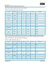
Table 6-2. Performance Effects of Memory Operand Placement
(Page 1 of 2)
Operand Boundary Crossing
Size Byte Alignment None 8 Byte Cache Block
Protection
Boundary
Integer
4 byte
4Optimal
1
———
< 4 Optimal Good
2
Good Good
2 byte
2 Optimal — — —
< 2 Optimal Good Good Good
1 byte 1 Optimal — — —
Load Multiple Word (lmw),
Store Multiple Word (stmw)
3
4 Good Good Good Good
< 4 Poor
4
Poor Poor Poor
String
3
— Good Good Good Good
Note:
1. Optimal means one EA calculation occurs.
2. Good means multiple EA calculations occur that might cause additional bus activities with multiple bus transfers.
3. Not supported in little-endian mode; causes an alignment exception.
4. Poor means that an alignment exception occurs.