


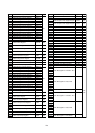


B-1
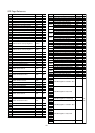
SFR Page Reference
PM0
PM1
CM0
CM1
AIER
PRCR
CM2
WDTS
WDC
RMAD0
RMAD1
PLC0
PM2
SAR0
DAR0
TCR0
DM0CON
SAR1
DAR1
TCR1
DM1CON
Address Register Symbol Page
The blank areas are reserved.
0000h
0001h
0002h
0003h
0004h
0005h
0006h
0007h
0008h
0009h
000Ah
000Bh
000Ch
000Dh
000Eh
000Fh
0010h
0011h
0012h
0013h
0014h
0015h
0016h
0017h
0018h
0019h
001Ah
001Bh
001Ch
001Dh
001Eh
001Fh
0020h
0021h
0022h
0023h
0024h
0025h
0026h
0027h
0028h
0029h
002Ah
002Bh
002Ch
002Dh
002Eh
002Fh
0030h
0031h
0032h
0033h
0034h
0035h
0036h
0037h
0038h
0039h
003Ah
003Bh
003Ch
003Dh
003Eh
003Fh
32
33
37
38
79
59
39
81
81
79
79
42
41
86
86
86
85
86
86
86
85
Processor Mode Register 0
Processor Mode Register 1
System Clock Control Register 0
System Clock Control Register 1
Address Match Interrupt Enable Register
Protect Register
Oscillation Stop Detection Register
Watchdog Timer Start Register
Watchdog Timer Control Register
Address Match Interrupt Register 0
Address Match Interrupt Register 1
PLL Control Register 0
Processor Mode Register 2
DMA0 Source Pointer
DMA0 Destination Pointer
DMA0 Transfer Counter
DMA0 Control Register
DMA1 Source Pointer
DMA1 Destination Pointer
DMA1 Transfer Counter
DMA1 Control Register
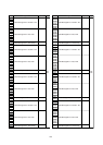
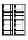
Address Register Symbol Page
C01WKIC
C0RECIC
C0TRMIC
INT3IC
TB5IC
S5IC
TB4IC
U1BCNIC
TB3IC
U0BCNIC
C1RECIC
S4IC
INT5IC
C1TRMIC
S3IC
INT4IC
U2BCNIC
DM0IC
DM1IC
C01ERRIC
ADIC
KUPIC
S2TIC
S2RIC
S0TIC
S0RIC
S1TIC
S1RIC
TA0IC
TA1IC
TA2IC
INT7IC
TA3IC
INT6IC
TA4IC
TB0IC
S6IC
TB1IC
INT8IC
TB2IC
INT0IC
INT1IC
INT2IC
0040h
0041h
0042h
0043h
0044h
0045h
0046h
0047h
0048h
0049h
004Ah
004Bh
004Ch
004Dh
004Eh
004Fh
0050h
0051h
0052h
0053h
0054h
0055h
0056h
0057h
0058h
0059h
005Ah
005Bh
005Ch
005Dh
005Eh
005Fh
0060h
0061h
0062h
0063h
0064h
0065h
0066h
0067h
0068h
0069h
006Ah
006Bh
006Ch
006Dh
006Eh
006Fh
0070h
0071h
0072h
0073h
0074h
0075h
0076h
0077h
0078h
0079h
007Ah
007Bh
007Ch
007Dh
007Eh
007Fh
65
65
65
66
65
65
65
65
65
65
66
66
66
66
66
66
65
65
65
65
65
65
65
65
65
65
65
65
65
65
66
66
66
66
65
65
65
66
66
65
66
66
66
204
205
CAN0/1 Wake-up Interrupt Control Register
CAN0 Successful Reception Interrupt Control Register
CAN0 Successful Transmission Interrupt Control Register
INT3 Interrupt Control Register
Timer B5 Interrupt Control Register
SI/O5 Interrupt Control Register
Timer B4 Interrupt Control Register
UART1 Bus Collision Detection Interrupt Control Register
Timer B3 Interrupt Control Register
UART0 Bus Collision Detection Interrupt Control Register
CAN1 Successful Reception Interrupt Control Register
SI/O4 Interrupt Control Register
INT5 Interrupt Control Register
CAN1 Successful Transmission Interrupt Control Register
SI/O3 Interrupt Control Register
INT4 Interrupt Control Register
UART2 Bus Collision Detection Interrupt Control Register
DMA0 Interrupt Control Register
DMA1 Interrupt Control Register
CAN0/1 Error Interrupt Control Register
A/D Conversion Interrupt Control Register
Key Input Interrupt Control Register
UART2 Transmit Interrupt Control Register
UART2 Receive Interrupt Control Register
UART0 Transmit Interrupt Control Register
UART0 Receive Interrupt Control Register
UART1 Transmit Interrupt Control Register
UART1 Receive Interrupt Control Register
Timer A0 Interrupt Control Register
Timer A1 Interrupt Control Register
Timer A2 Interrupt Control Register
INT7 Interrupt Control Register
Timer A3 Interrupt Control Register
INT6 Interrupt Control Register
Timer A4 Interrupt Control Register
Timer B0 Interrupt Control Register
SI/O6 Interrupt Control Register
Timer B1 Interrupt Control Register
INT8 Interrupt Control Register
Timer B2 Interrupt Control Register
INT0 Interrupt Control Register
INT1 Interrupt Control Register
INT2 Interrupt Control Register
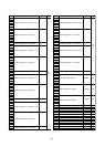
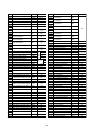
CAN0 Message Box 0: Identifier / DLC
CAN0 Message Box 0: Data Field
CAN0 Message Box 0: Time Stamp
CAN0 Message Box 1: Identifier / DLC
CAN0 Message Box 1: Data Field
CAN0 Message Box 1: Time Stamp