


Rev.1.10 Jul 01, 2005 page 106 of 318
REJ09B0124-0110
M16C/6N Group (M16C/6NK, M16C/6NM) 12. Timers
Under development
This document is under development and its contents are subject to change.
12.1.4 Pulse Width Modulation (PWM) Mode
In pulse width modulation mode, the timer outputs pulses of a given width in succession. The counter
functions as either 16-bit pulse width modulator or 8-bit pulse width modulator.
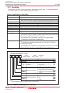
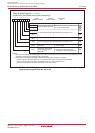
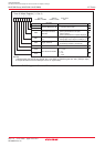
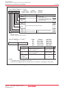
Table 12.5 lists specifications in pulse width modulation mode. Figure 12.12 shows TAiMR register in
pulse width modulation mode.
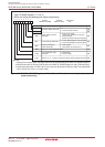
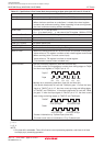
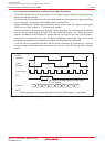
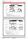
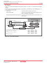
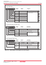
Figures 12.13 and 12.14 show examples of how a 16-bit pulse width modulator operates and how an 8-bit
pulse width modulator operates, respectively.
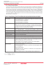
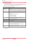
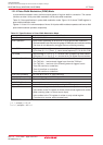
Table 12.5 Specifications in Pulse Width Modulation Mode
Item Specification
Count Source f1, f2, f8, f32, fC32
Count Operation • Down-count (operating as an 8-bit or a 16-bit pulse width modulator)
• The timer reloads a new value at a rising edge of PWM pulse and continues counting
• The timer is not affected by a trigger that occurs during counting
16-bit PWM • High level width n / fj n : set value of the TAi register
• Cycle time (2
16
-1) / fj fixed fj : count source frequency (f1, f2, f8, f32, fC32)
8-bit PWM • High level width n ✕ (m+1) / fj n :
set value of the TAi register high-order address
• Cycle time (2
8
-1) ✕ (m+1) / fj m :
set value of the TAi register low-order address
Count Start Condition • The TAiS bit in the TABSR register is set to “1” (start counting)
• The TAiS bit = 1 and external trigger input from the TAiIN pin
• The TAiS bit = 1 and one of the following external triggers occurs
Timer B2 overflow or underflow,
Timer Aj overflow or underflow,
Timer Ak overflow or underflow
Count Stop Condition The TAiS bit is set to “0” (stop counting)
Interrupt Request Generation Timing
On the falling edge of the PWM pulse
TAiIN Pin Function I/O port or trigger input
TAiOUT Pin Function Pulse output
Read from Timer An indeterminate value is read by reading the TAi register
Write to Timer • When not counting and until the 1st count source is input after counting start
Value written to the TAi register is written to both reload register and counter
• When counting (after 1st count source input)
Value written to the TAi register is written to only reload register
(Transferred to counter when reloaded next)
i = 0 to 4
j = i - 1, except j = 4 if i = 0
k = i + 1, except k = 0 if i = 4