


Rev.1.10 Jul 01, 2005 page 46 of 318
REJ09B0124-0110
M16C/6N Group (M16C/6NK, M16C/6NM) 7. Clock Generating Circuit
Under development
This document is under development and its contents are subject to change.
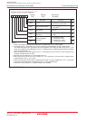
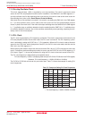
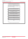
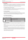
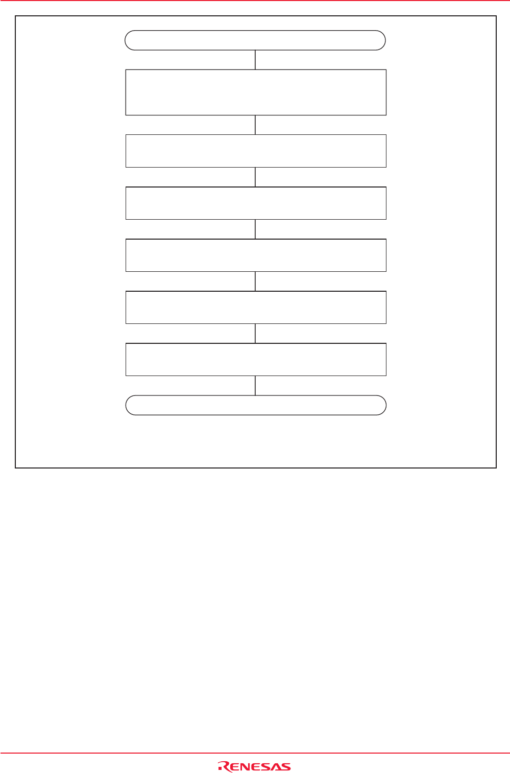
Figure 7.11 Procedure to Use PLL Clock as CPU Clock Source
Set the PLC02 to PLC00 bits (multiplying factor).
(When PLL clock > 16 MHz)
Set the PM20 bit to "0" (2-wait state).
Set the PLC07 bit to "1" (PLL operation).
Set the CM11 bit to "1" (PLL clock for the CPU clock source).
END
Using the PLL clock as the clock source for the CPU
Set the CM07 bit to "0" (main clock), the CM17 to CM16
bits to "00b" (main clock undivided), and the CM06 bit to "0"
(CM16 and CM17 bits enabled).
(1)
NOTE:
1. PLL operation mode can be entered from high-speed mode.
Wait until the PLL clock becomes stable (tsu(PLL)).