


Rev.1.10 Jul 01, 2005 page 101 of 318
REJ09B0124-0110
M16C/6N Group (M16C/6NK, M16C/6NM) 12. Timers
Under development
This document is under development and its contents are subject to change.
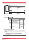
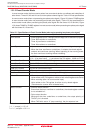
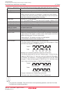
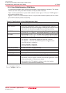
Item Specification
Count Source • Two-phase pulse signals input to TAiIN or TAiOUT pins
Count Operation • Up-count or down-count can be selected by two-phase pulse signal
• When the timer overflows or underflows, it reloads the reload register
contents and continues counting. When operating in free-running mode,
the timer continues counting without reloading.
Divide Ratio 1/ (FFFFh - n + 1) for up-count
1/ (n + 1) for down-count n : set value of the TAi register 0000h to FFFFh
Count Start Condition Set the TAiS bit in the TABSR register to “1” (start counting)
Count Stop Condition Set the TAiS bit to “0” (stop counting)
Interrupt Request Generation Timing
Timer overflow or underflow
TAiIN Pin Function Two-phase pulse input
TAiOUT Pin Function Two-phase pulse input
Read from Timer Count value can be read by reading the TAi register
Write to Timer • When not counting and until the 1st count source is input after counting start
Value written to TAi register is written to both reload register and counter
• When counting (after 1st count source input)
Value written to TAi register is written to reload register
(Transferred to counter when reloaded next)
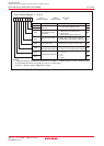
Select Function
(1)
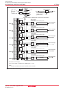
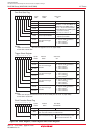
• Normal processing operation (timer A2 and timer A3)
The timer counts up rising edges or counts down falling edges on TAjIN
pin when input signals on TAjOUT pin is “H”.
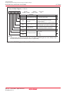
Table 12.3
Specifications in Event Counter Mode (when processing two-phase pulse signal with timers A2, A3 and A4)
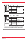
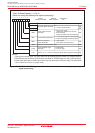
• Counter initialization by Z-phase input (timer A3)
The timer count value is initialized to “0” by Z-phase input.
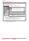
Up-
count
Up-
count
Up-
count
Down-
count
Down-
count
Down-
count
TAjOUT
TAjIN
Count up all edges
Count up all edges
Count down all edges
Count down all edges
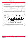
TAkOUT
TAkIN
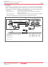
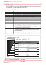
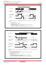
• Multiply-by-4 processing operation (timer A3 and timer A4)
If the phase relationship is such that TAkIN pin goes “H” when the input
signal on TAkOUT pin is “H”, the timer counts up rising and falling edges
on TAkOUT and TAkIN pins. If the phase relationship is such that TAkIN
pin goes “L” when the input signal on TAkOUT pin is “H”, the timer counts
down rising and falling edges on TAkOUT and TAkIN pins.
i = 2 to 4
j = 2, 3
k = 3, 4
NOTE:
1. Only timer A3 is selectable. Timer A2 is fixed to normal processing operation, and timer A4 is fixed
to multiply-by-4 processing operation.