


Rev.1.10 Jul 01, 2005 page 271 of 318
REJ09B0124-0110
M16C/6N Group (M16C/6NK, M16C/6NM) 21. Electric Characteristics
Under development
This document is under development and its contents are subject to change.
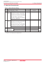
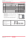
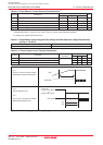
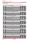
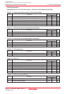
Table 21.3 Recommended Operating Conditions (2)
(1)
Main Clock Input Oscillation No Wait Mask ROM Version VCC = 3.0 to 5.5V
Frequency
(2) (3) (4)
Flash Memory Version
Sub Clock Oscillation Frequency
On-chip Oscillation Frequency
PLL Clock Oscillation Frequency
CPU Operation Clock
VCC = 3.0 to 5.5V
PLL Frequency Synthesizer Stabilization Wait Time
Power Supply Ripple Allowable Frequency (VCC)
Power Supply Ripple Allowable Amplitude Voltage VCC = 5V
VCC = 3V
Power Supply Ripple Rising/Falling Gradient VCC = 5V
VCC = 3V
32.768
1
MHz
kHz
MHz
MHz
MHz
ms
kHz
V
V/ms
0
16
0
16
50
24
24
20
10
0.5
0.3
0.3
0.3
f(XIN)
f(XCIN)
f(Ring)
f(PLL)
f(BCLK)
t
su(PLL)
f(ripple)
VP-P(ripple)
VCC(|∆V/∆T|)
ParameterSymbol
Typ.Min.
Standard
Unit
Max.
NOTES:
1. Referenced to VCC = 3.0 to 5.5V at Topr = –40 to 85°C unless
otherwise specified.
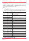
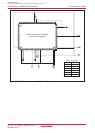
2. Relationship between main clock oscillation frequency and supply
voltage is shown right.
3. Execute program/erase of flash memory by VCC = 3.3 ± 0.3 V or
VCC = 5.0 ± 0.5 V.
4. When using 16MHz and over, use PLL clock. PLL clock oscillation
frequency which can be used is 16MHz, 20MHz or 24MHz.
0.0
16.0
5.53.0
VCC [V] (main clock: no division)
Main clock input oscillation frequency
f(XIN) operating maximum frequency [MHz]
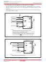
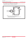
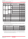
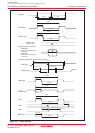
f(ripple)
Power Supply Ripple Allowable
Frequency (VCC)
V
P-P(ripple)
Power Supply Ripple Allowable
Amplitude Voltage
Figure 21.1 Timing of Voltage Fluctuation
f
(ripple)
V
P-P(ripple)
VCC