


Rev.1.10 Jul 01, 2005 page 96 of 318
REJ09B0124-0110
M16C/6N Group (M16C/6NK, M16C/6NM) 12. Timers
Under development
This document is under development and its contents are subject to change.
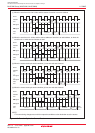
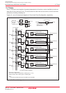
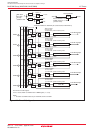
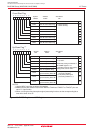
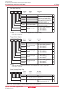
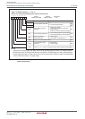
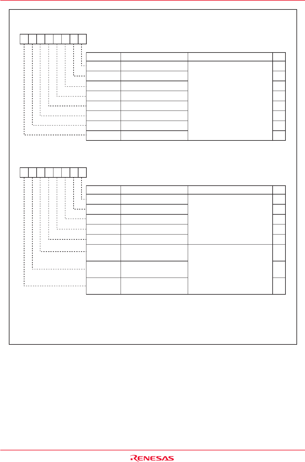
Figure 12.5 TABSR Register and UDF Register
Timer A4 Up/Down Flag
Timer A3 Up/Down Flag
Timer A2 Up/Down Flag
Timer A1 Up/Down Flag
Timer A0 Up/Down Flag
Timer A2 Two-Phase Pulse
Signal Processing Select Bit
Timer A3 Two-Phase Pulse
Signal Processing Select Bit
Timer A4 Two-Phase Pulse
Signal Processing Select Bit
Symbol Address After Reset
UDF 0384h 00h
TA4P
TA3P
TA2P
Up/Down Flag
(1)
Bit Name FunctionBit Symbol
b7 b6 b5 b4 b3 b2 b1 b0
TA4UD
TA3UD
TA2UD
TA1UD
TA0UD
0 : Down count
1 : Up count
Enabled by setting the MR2 bit in
the TAiMR register to "0"
(= switching source in UDF register)
during event counter mode.
0 : Two-phase pulse signal
processing disabled
1 : Two-phase pulse signal
processing enabled
(2) (3)
Symbol Address After Reset
TABSR 0380h 00h
Count Start Flag
Bit Name FunctionBit Symbol
RW
b7 b6 b5 b4 b3 b2 b1 b0
Timer B2 Count Start Flag
Timer B1 Count Start Flag
Timer B0 Count Start Flag
Timer A4 Count Start Flag
Timer A3 Count Start Flag
Timer A2 Count Start Flag
Timer A1 Count Start Flag
TB2S
TB1S
TB0S
TA4S
TA3S
TA2S
TA1S
TA0S
RW
RW
RW
RW
RW
RW
RW
RW
RW
RW
RW
RW
RW
RW
WO
WO
WO
NOTES:
1.Use the MOV instruction to write to this register.
2.Make sure the port direction bits for the TA2IN to TA4IN and TA2OUT to TA4OUT pins are
set to "0" (input mode).
3.When not using the two-phase pulse signal processing function, set the corresponding bit to
timer A2 to timer A4 to "0".
Timer A0 Count Start Flag 0 : Stops counting
1 : Starts counting