


Rev.1.10 Jul 01, 2005 page 311 of 318
REJ09B0124-0110
M16C/6N Group (M16C/6NK, M16C/6NM) 22. Usage Precaution
Under development
This document is under development and its contents are subject to change.
22.18 Flash Memory Version
22.18.1 Functions to Prevent Flash Memory from Rewriting
ID codes are stored in addresses 0FFFDFh, 0FFFE3h, 0FFFEBh, 0FFFEFh, 0FFFF3h, 0FFFF7h, and
0FFFFBh. If wrong data are written to theses addresses, the flash memory cannot be read or written in
standard serial I/O mode and CAN I/O mode.
The ROMCP register is mapped in address 0FFFFFh. If wrong data is written to this address, the flash
memory cannot be read or written in parallel I/O mode.
In the flash memory version of microcomputer, these addresses are allocated to the vector addresses (H)
of fixed vectors.
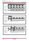
22.18.2 Stop Mode
When entering stop mode, the following settings are required:
• Set the FMR01 bit to “0” (CPU rewrite mode disabled). Disable DMA transfer before setting the CM10 bit
to “1” (stop mode).
• Execute the instruction to set the CM10 bit to “1” (stop mode) and then the JMP.B instruction.
Example program BSET 0, CM1 ; Stop mode
JMP.B L1
L1:
Program after exiting stop mode
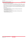
22.18.3 Wait Mode
When entering wait mode, set the FMR01 bit in the FMR0 register to “0” (CPU rewrite mode disabled)
before executing the WAIT instruction.
22.18.4 Low Power Dissipation Mode and On-Chip Oscillator Low Power Dissipation Mode
If the CM05 bit is set to “1” (main clock stopped), do not execute the following commands:
• Program
• Block erase
• Erase all unlocked blocks
• Lock bit program software command
• Read lock bit status
22.18.5 Writing Command and Data
Write commands and data to even addresses in the user ROM area.
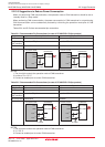
22.18.6 Program Command
By writing “xx40h” in the first bus cycle and data to the write address in the second bus cycle, an auto
program operation (data program and verify) will start. The address value specified in the first bus cycle
must be the same even address as the write address specified in the second bus cycle.
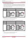
22.18.7 Lock Bit Program Command
By writing “xx77h” in the first bus cycle and “xxD0h” to the highest-order even address of a block in the
second bus cycle, the lock bit for the specified block is set to “0”. The address value specified in the first
bus cycle must be the same highest-order even address of a block specified in the second bus cycle.