


Rev.1.10 Jul 01, 2005 page 236 of 318
REJ09B0124-0110
M16C/6N Group (M16C/6NK, M16C/6NM) 19. Programmable I/O Ports
Under development
This document is under development and its contents are subject to change.
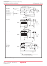
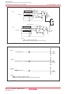
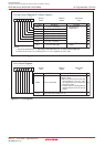
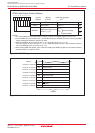
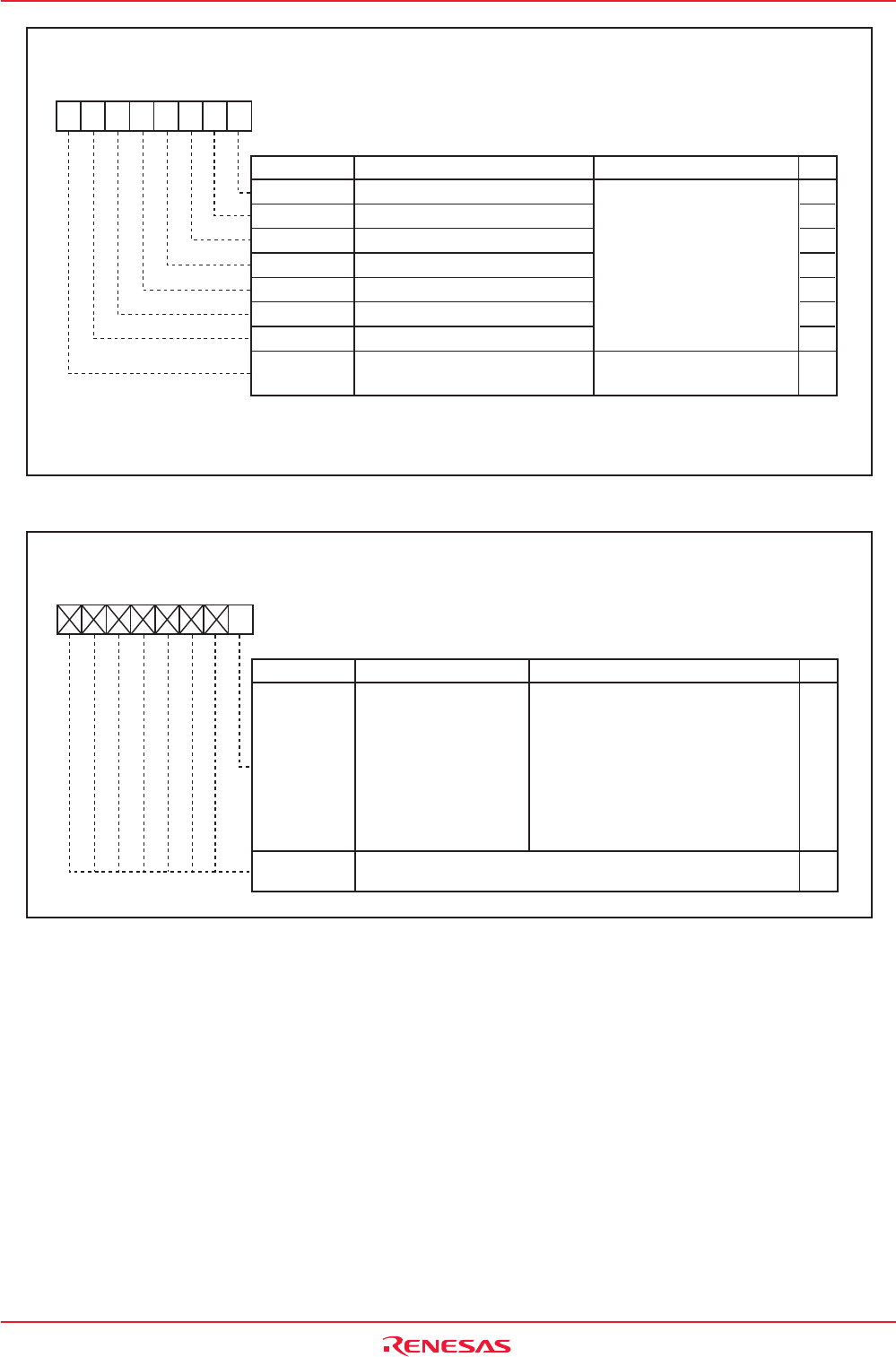
Figure19.10 PUR3 Register
Pull-up Control Register 3 (128-pin version)
Bit NameBit Symbol RW
b7 b6 b5 b4 b3 b2 b1 b0
PUR3
03DFh
00h
Symbol Address After Reset
NOTES:
1. The pin for which this bit is "1" (pulled high) and the direction bit is "0" (input mode) is pulled high.
2. If the PU37 bit is set to "0" (unusable), the P11 to P14 regisrers are set to "00h".
PU30
PU31
PU32
PU33
PU34
PU35
PU36
PU37
P11_0 to P11_3 Pull-Up
P11_4 to P11_7 Pull-Up
P12_0 to P12_3 Pull-Up
P12_4 to P12_7 Pull-Up
P13_0 to P13_3 Pull-Up
P13_4 to P13_7 Pull-Up
P14_0, P14_1 Pull-Up
P11 to P14 Enabling Bit
0 : Not pulled high
1 : Pulled high
(1)
0 : Unusable
(2)
1 : Usable
RW
RW
RW
RW
RW
RW
RW
RW
Function
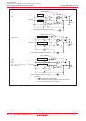
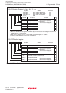
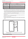
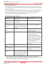
Figure19.11 PCR Register
Port Control Register
Bit NameBit Symbol RW
b7 b6 b5 b4 b3 b2 b1 b0
PCR
03FFh
00h
Symbol Address After Reset
PCR0
-
(b7-b1)
Port P1 Control Bit
Operation performed when the P1
register is read
0 : When the port is set for input, the
input levels of P1_0 to P1_7 pins
are read. When set for output, the
port latch is read.
1 : The port latch is read regardless of
whether the port is set for input or
output.
RW
-
Function
Nothing is assigned. When write, set to "0".
When read, their contents are "0".