


Rev.1.10 Jul 01, 2005 page 120 of 318
REJ09B0124-0110
M16C/6N Group (M16C/6NK, M16C/6NM) 13. Three-Phase Motor Control Timer Function
Under development
This document is under development and its contents are subject to change.
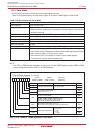
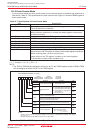
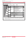
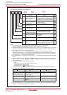
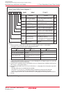
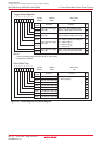
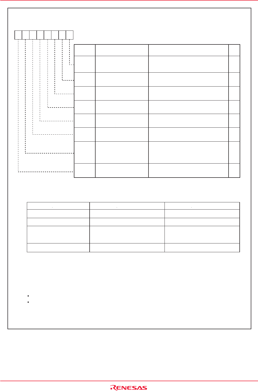
Figure 13.3 INVC1 Register
INV10
INV11
INV12
INV13
INV15
TA11, TA21 and TA41 Registers
INV00 and INV01 Bit
Not used Used
INV14
Function
Three-Phase PWM Control Register 1
(1)
Timer A1, A2 and A4
Start Trigger Select Bit
Carrier Wave Detect
Flag
(4)
Dead Time Timer
Trigger Select Bit
INV13 Bit Disabled
Enabled
Output Polarity Control
Bit
0: Timer A1 reload control signal is "0"
1: Timer A1 reload control signal is "1"
Timer A1-1, A2-1, A4-1
Control Bit
(2)
0: Three-phase mode 0
(3)
1: Three-phase mode 1
Dead Time Timer
Count Source Select Bit
0 : f1 or f2
1 : f1 divided-by-2 or f2 divided-by-2
0: Timer B2 underflow
1: Timer B2 underflow and write to
the timer B2
0 : Active "L" of an output waveform
1 : Active "H" of an output waveform
Dead Time Disable Bit
0: Enables dead time
1: Disables dead time
Bit Name
Bit
Symbol
Symbol Address After Reset
INVC1 01C9h 00h
RW
RW
RW
RW
RO
RW
RW
RW
Reserved Bit Set to "0"
RW
Item INV11 = 0 INV11 = 1
NOTES:
1. Rewrite the INVC1 register after the PRC1 bit in the PRCR register is set to "1" (write enable).
The timers A1, A2, A4, and B2 must be stopped during rewrite.
2. The following table lists how the INV11 bit works.
3. When the INV06 bit is set to "1" (sawtooth wave modulation mode), set the INV11 bit to "0" (three-phase
mode 0). Also, when the INV11 bit is set to "0", set the PWCON bit in the TB2SC register to "0" (timer B2
is reloaded when the timer B2 underflows).
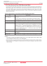
4. The INV13 bit is enabled only when the INV06 bit is set to "0" (Triangular wave modulation mode) and the
INV11 bit to "1" (three-phase mode 1).
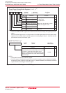
5. If the following conditions are all met, set the INV16 bit to "1" (rising edge of the three-phase output shift
register).
The INV15 bit is set to "0" (dead time timer enabled)
The Dij bit (i=U, V or W, j=0, 1) and DiBj bit always have different values when the INV03 bit
is set to "1". (The positive-phase and negative-phase always output opposite level signals.)
If above conditions are not met, set the INV16 bit to "0" (falling edge of a one-shot pulse of the timer A1,
A2, A4).
Disabled. The ICTB2 counter is
incremented whenever the timer B2
underflows
0: Falling edge of a one-shot pulse of
the timer A1, A2, A4
(5)
1: Rising edge of the three-phase output
shift register (U-, V-, W-phase)
INV16
-
(b7)
Enabled when INV11=1 and INV06=0
Three-phase mode 0 Three-phase mode 1Mode
b7 b6 b5 b4 b3 b2 b1 b0
0