


Rev.1.10 Jul 01, 2005 page 292 of 318
REJ09B0124-0110
M16C/6N Group (M16C/6NK, M16C/6NM) 22. Usage Precaution
Under development
This document is under development and its contents are subject to change.
22.9.1.3 Timer A (One-shot Timer Mode)
The timer remains idle after reset. Set the mode, count source, counter value, etc. using the TAiMR
(i = 0 to 4) register, the TAi register, the TA0TGL and TA0TGH bits in the ONSF register and the TRGSR
register before setting the TAiS bit in the TABSR register to “1” (count starts).
Always make sure the TAiMR register, the TA0TGL and TA0TGH bits and the TRGSR register are
modified while the TAiS bit remains “0” (count stops) regardless whether after reset or not.
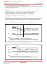
When setting the TAiS bit to “0” (count stop), the followings occur:
• A counter stops counting and a content of reload register is reloaded.
• TAiOUT pin outputs “L”.
• After one cycle of the CPU clock, the IR bit in the TAiIC register is set to “1” (interrupt request).
Output in one-shot timer mode synchronizes with a count source internally generated. When an external
trigger has been selected, one-cycle delay of a count source as maximum occurs between a trigger
input to TAiIN pin and output in one-shot timer mode.
The IR bit is set to “1” when timer operation mode is set with any of the following procedures:
• Select one-shot timer mode after reset.
• Change an operation mode from timer mode to one-shot timer mode.
• Change an operation mode from event counter mode to one-shot timer mode.
To use the Timer Ai interrupt (the IR bit), set the IR bit to “0” after the changes listed above have been
made.
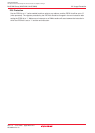
When a trigger occurs, while counting, a counter reloads the reload register to continue counting after
generating a re-trigger and counting down once. To generate a trigger while counting, generate a second
trigger between occurring the previous trigger and operating longer than one cycle of a timer count
source.
When the external trigger is selected as count start condition, do not input again the external trigger
between 300 ns before the counter reachs “0000h”.
______
If a low-level signal is applied to the NMI pin when the IVPCR1 bit in the TB2SC register = 1 (three-
______
phase output forcible cutoff by input on NMI pin enabled), the TA1OUT, TA2OUT and TA4OUT pins go
to a high-impedance state.