


Rev.1.10 Jul 01, 2005 page 127 of 318
REJ09B0124-0110
M16C/6N Group (M16C/6NK, M16C/6NM) 13. Three-Phase Motor Control Timer Function
Under development
This document is under development and its contents are subject to change.
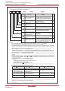
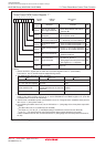
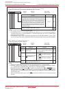
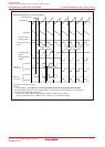
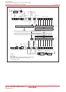
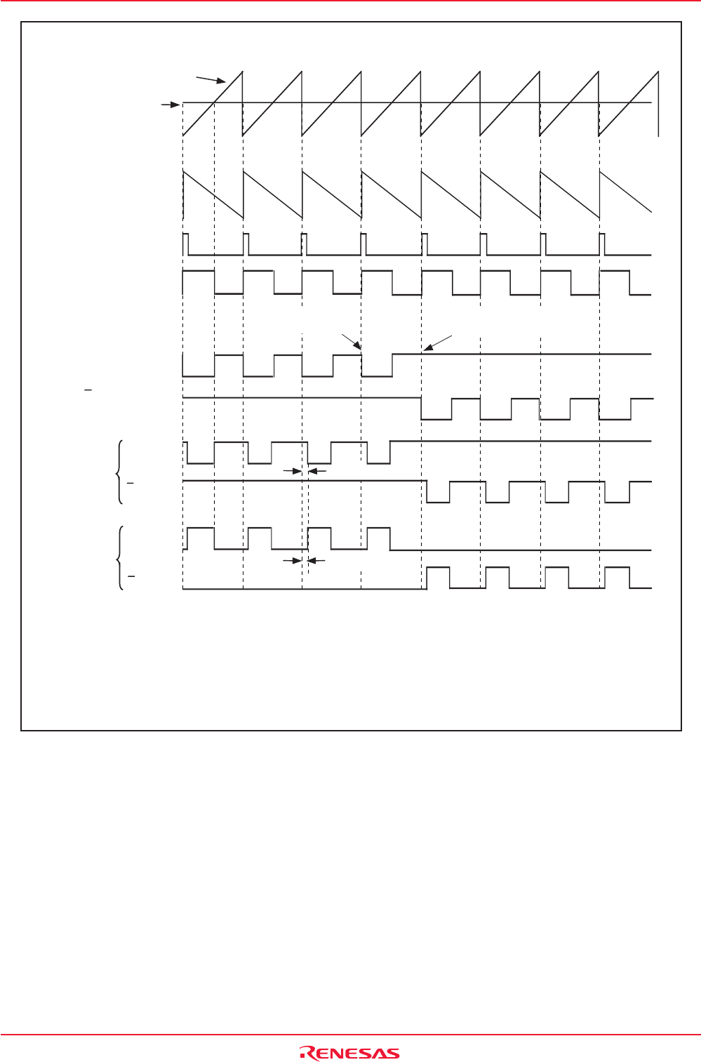
Figure 13.10 Sawtooth Wave Modulation Operation
Timer B2
U-Phase
Sawtooth Wave
Signal Wave
U-Phase Output
Signal
(1)
U-Phase Output
Signal
(1)
INV14 = 0
("L" active)
Sawtooth Waveform as a Carrier Wave
Transfer the counter to the
three-phase shift register
Rewrite the IDB0
and IDB1 registers
NOTES:
1. Internal signals. See Figure 13.1 Three-Phase Motor Control Timer Functions Block Diagram.
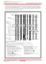
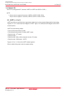
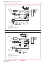
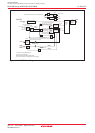
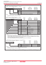
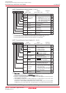
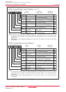
The examples of PWM output change are
- Default value of the IDB0 and IDB1 registers: DU0=0, DUB0=1, DU1=1, DUB1=1
They are changed to DU0=1, DUB0=0, DU1=1, DUB1=1 by the timer B2 interrupt.
The above applies to INVC0 = 01XX110Xb and INVC1 = 010XXX00b (X varies depending on each system.)
INV14 = 1
("H" active)
U-Phase
U-Phase
U-Phase
Dead time
Dead time
Timer A4 One-Shot
Pulse
(1)
Timer A4 Start
Trigger Signal
(1)
INV14: Bits in the INVC1 register