


Rev.1.10 Jul 01, 2005 page 128 of 318
REJ09B0124-0110
M16C/6N Group (M16C/6NK, M16C/6NM) 14. Serial I/O
Under development
This document is under development and its contents are subject to change.
14. Serial I/O
Serial I/O is configured with 7 channels: UART0 to UART2 and SI/O3 to SI/O6
(1)
.
NOTE:
1. 100-pin version supports 5 channels; UART0 to UART2, SI/O3, SI/O4
128-pin version supports 7 channels; UART0 to UART2, SI/O3 to SI/O6
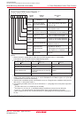
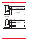
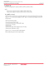
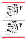
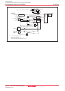
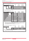
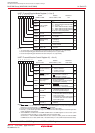
14.1 UARTi (i = 0 to 2)
UARTi each have an exclusive timer to generate a transfer clock, so they operate independently of each other.
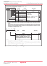
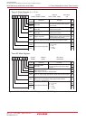
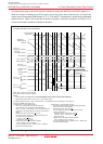
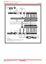
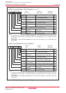
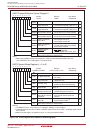
Figures 14.1 to 14.3 show the block diagram of UARTi. Figure 14.4 shows the block diagram of the UARTi
transmit/receive.
UARTi has the following modes:
• Clock synchronous serial I/O mode
• Clock asynchronous serial I/O mode (UART mode).
• Special mode 1 (I
2
C mode)
• Special mode 2
• Special mode 3 (Bus collision detection function, IE mode)
• Special mode 4 (SIM mode) : UART2
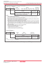
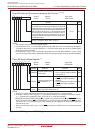
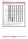
Figures 14.5 to 14.10 show the UARTi-related registers.
Refer to tables listing each mode for register setting.