


Rev.1.10 Jul 01, 2005 page 208 of 318
REJ09B0124-0110
M16C/6N Group (M16C/6NK, M16C/6NM) 18. CAN Module
Under development
This document is under development and its contents are subject to change.
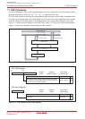
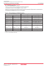
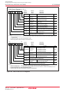
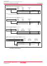
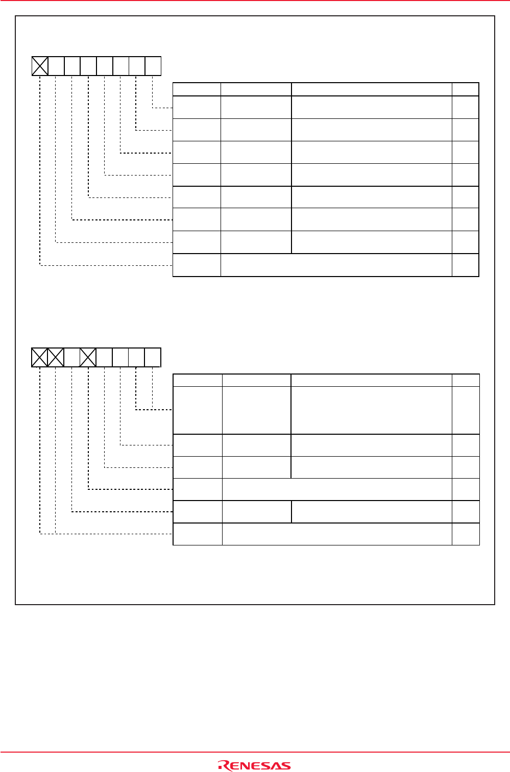
Figure 18.7 C0CTLR and C1CTLR Registers
FunctionBit Symbol
Reset
CAN Module
Reset Bit
(1)
Loop Back Mode
Select Bit
(2)
LoopBack
Message Order
Select Bit
(2)
MsgOrder
BasicCAN
Basic CAN Mode
Select Bit
(2)
BusErrEn
Bus Error Interrupt
Enable Bit
(2)
Sleep
Sleep Mode
Select Bit
(2) (3)
CAN Port Enable
Bit
(2) (3)
PortEn
-
(b7)
CANi Control Register (i = 0, 1)
Symbol
Address After Reset
C0CTLR
C1CTLR
X0000001b
X0000001b
0210h
0230h
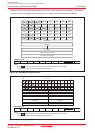
Symbol
Address After Reset
C0CTLR
C1CTLR
XX0X0000b
XX0X0000b
0211h
0231h
b7 b6 b5 b4 b3 b2 b1 b0
NOTES:
1. When the Reset bit is set to "1" (CAN reset/initialization mode), check that the State_Reset bit in the CiSTR register is set to
"1" (Reset mode).
2. Change this bit only in the CAN reset/initialization mode.
3. When using CAN0/1 wake-up interrupt, set these bits to "1".
RW
RW
RW
RW
RW
RW
RW
RW
-
0: Operation mode
1: Reset/initialization mode
0: Word access
1: Byte access
0: Basic CAN mode disabled
1: Basic CAN mode enabled
0: Loop back mode disabled
1: Loop back mode enabled
0: Bus error interrupt disabled
1: Bus error interrupt enabled
0: Sleep mode disabled
1: Sleep mode enabled; clock supply stopped
0: I/O port function
1: CTX/CRX function
(b15) (b8)
b7 b6 b5 b4 b3 b2 b1 b0
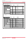
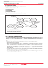
TSPreScale
TSReset
RXOnly
RetBusOff
Nothing is assigned. When write, set to "0".
When read, its content is indeterminate.
Nothing is assigned. When write, set to "0".
When read, their contents are indeterminate.
b1 b0
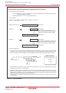
NOTES:
1. When the TSReset bit = 1, the CiTSR register is set to "0000h". After this, the bit is automatically set to "0".
2. When the RetBusOff bit = 1, the CiRECR and CiTECR registers are set to "00h". After this, this bit is automatically set to "0".
3. Change this bit only in the CAN reset/initialization mode.
4. When the listen-only mode is selected, do not request the transmission.
RW
RW
RW
RW
-
RW
-
0 0: Period of 1 bit time
0 1: Period of 1/2 bit time
1 0: Period of 1/4 bit time
1 1: Period of 1/8 bit time
0: Nothing is occurred.
1: Force reset of the time stamp counter
0: Listen-only mode disabled
1: Listen-only mode enabled
(4)
0: Nothing is occurred.
1: Force return from bus off
Time Stamp
Prescaler
(3)
Time Stamp Counter
Reset Bit
(1)
Return From Bus Off
Command Bit
(2)
Listen-Only Mode
Select Bit
(3)
Nothing is assigned. When write, set to "0".
When read, its content is indeterminate.
-
(b4)
-
(b7-b6)
Bit Name
FunctionBit Symbol Bit Name