


Rev.1.10 Jul 01, 2005 page 70 of 318
REJ09B0124-0110
M16C/6N Group (M16C/6NK, M16C/6NM) 9. Interrupt
Under development
This document is under development and its contents are subject to change.
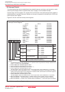
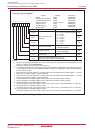
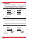
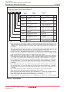
9.5.7 Saving Registers
In the interrupt sequence, the FLG register and PC are saved to the stack.
At this time, the 4 high-order bits of the PC and the 4 high-order (IPL) and 8 low-order bits in the FLG
register, 16 bits in total, are saved to the stack first. Next, the 16 low-order bits of the PC are saved. Figure
9.7 shows the stack status before and after an interrupt request is accepted.
The other necessary registers must be saved in a program at the beginning of the interrupt routine. Use
the PUSHM instruction, and all registers except SP can be saved with a single instruction.
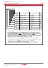
Figure 9.7 Stack Status Before and After Acceptance of Interrupt Request
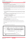
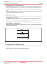
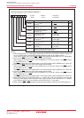
The operation of saving registers carried out in the interrupt sequence is dependent on whether the SP
(1)
,
at the time of acceptance of an interrupt request, is even or odd. If the SP (Note) is even, the FLG register
and the PC are saved, 16 bits at a time. If odd, they are saved in two steps, 8 bits at a time. Figure 9.8
shows the operation of the saving registers.
NOTE:
1. When any INT instruction in software numbers 32 to 63 has been executed, this is the SP indicated
by the U flag. Otherwise, it is the ISP.
m
-
4
m
-
3
m
-
2
m
-
1
m
m + 1
[SP]
SP value before
interrupt request
is accepted.
Stack status before interrupt request is acknowledged
Address
MSB LSB
Stack
m
-
4
m
-
3
m
-
2
m
-
1
m
m + 1
[SP]
New SP value
Stack status after interrupt request is acknowledged
Address
MSB LSB
Stack
PCL
PCM
FLGL
Content of previous stack
Content of previous stack
Content of previous stack
Content of previous stack
FLGH PCH
PCL : 8 low-order bit of PC
PCM : 8 middle-order bits of PC
PCH : 4 high-order bits of PC
FLGL : 8 low-order bits of FLG
FLGH: 4 high-order bits of FLG
Figure 9.8 Operation of Saving Registers
[SP]
-
5 (Odd)
[SP]
-
4 (Even)
[SP]
-
3 (Odd)
[SP]
-
2 (Even)
[SP]
-
1 (Odd)
[SP]
(Even)
[SP]
-
5 (Even)
[SP]
-
4 (Odd)
[SP]
-
3 (Even)
[SP]
-
2 (Odd)
[SP]
-
1 (Even)
[SP]
(Odd)
(2)
Saved simultaneously,
all 16 bits
(1)
Saved simultaneously,
all 16 bits
Address
Stack
Sequence in which order
registers are saved
Sequence in which order
registers are saved
Address
Stack
PCL
PCM
FLGL
NOTE:
1. [SP] denotes the initial value of the SP when interrupt request is acknowledged. After registers are saved, the SP content is [SP] minus 4.
FLGH PCH
PCL
PCM
FLGL
FLGH PCH
(1)SP contains even number (2)SP contains odd number
Finished saving registers
in two operations.
Finished saving registers
in four operations.
(3)
(4)
(1)
(2)
Saved,8 bits
at a time
PCL : 8 low-order bit of PC
PCM : 8 middle-order bits of PC
PCH : 4 high-order bits of PC
FLGL : 8 low-order bits of FLG
FLGH: 4 high-order bits of FLG