


Rev.1.10 Jul 01, 2005 page 220 of 318
REJ09B0124-0110
M16C/6N Group (M16C/6NK, M16C/6NM) 18. CAN Module
Under development
This document is under development and its contents are subject to change.
18.11 Basic CAN Mode
When the BasicCAN bit in the CiCTLR register (i = 0, 1) is set to “1” (Basic CAN mode enabled), slots 14
and 15 correspond to Basic CAN mode. In normal operation mode, each slot can handle only one type
message at a time, either a data frame or a remote frame by setting CiMCTLj regisrer (j = 0 to 15).
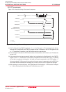
However, in Basic CAN mode, slots 14 and 15 can receive both types of message at the same time.
When slots 14 and 15 are defined as reception slots in Basic CAN mode, received messages are stored in
slots 14 and 15 alternately.
Which type of message has been received can be checked by the RemActive bit in the CiMCTLj register.
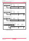
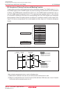
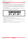
Figure 18.19 shows the operation of slots 14 and 15 in Basic CAN mode.
Figure 18.19 Operation of Slots 14 and 15 in Basic CAN Mode
When using Basic CAN mode, note the following points.
(1) Setting of Basic CAN mode has to be done in CAN reset/initialization mode.
(2) Select the same ID for slots 14 and 15. Also, setting of the CiLMAR and CiLMBR register has to be the
same.
(3) Define slots 14 and 15 as reception slot only.
(4) There is no protection available against message overwrite. A message can be overwritten by a new
message.
(5) Slots 0 to 13 can be used in the same way as in normal CAN operation mode.
Slot 14
Slot 15
Msg n Msg n+1 Msg n+2
Empty
Locked (empty) Locked (empty)
Msg n
Locked
Msg n + 1
Msg n+2
(Msg n lost)
Locked (Msg n+1
)
(Msg n)