


Rev.1.10 Jul 01, 2005 page 103 of 318
REJ09B0124-0110
M16C/6N Group (M16C/6NK, M16C/6NM) 12. Timers
Under development
This document is under development and its contents are subject to change.
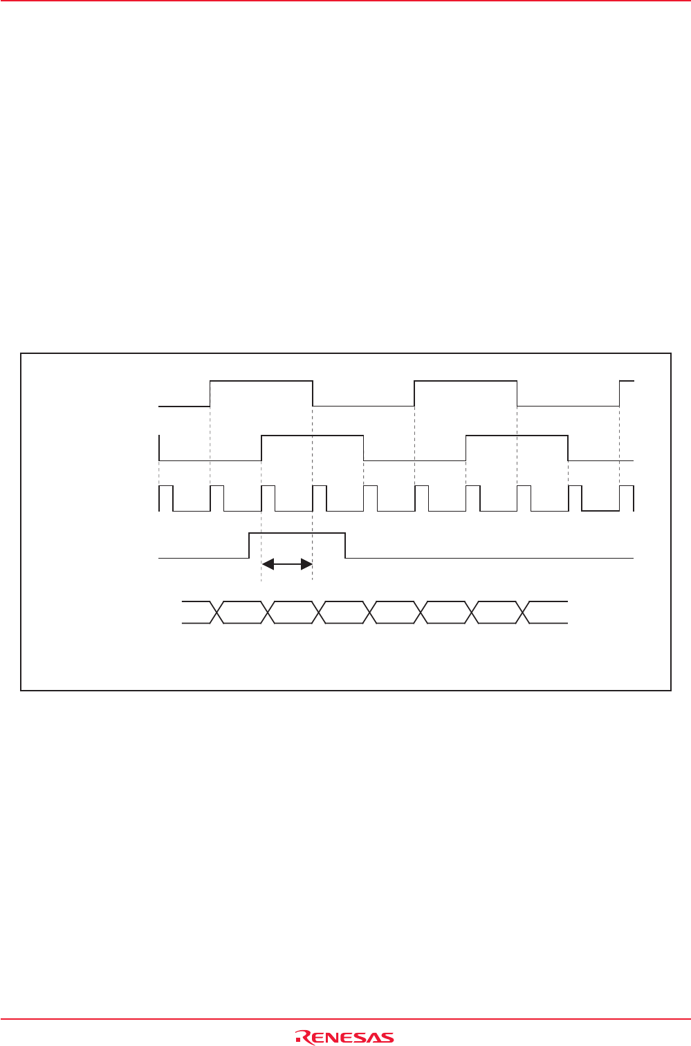
12.1.2.1 Counter Initialization by Two-Phase Pulse Signal Processing
This function initializes the timer count value to “0” by Z-phase (counter initialization) input during two-
phase pulse signal processing.
This function can only be used in timer A3 event counter mode during two-phase pulse signal processing,
free-running type, x4 processing, with Z-phase entered from the ZP pin.
Counter initialization by Z-phase input is enabled by writing “0000h” to the TA3 register and setting the
TAZIE bit in the ONSF register to “1” (Z-phase input enabled).
Counter initialization is accomplished by detecting Z-phase input edge. The active edge can be selected
to be the rising or falling edge by using the POL bit in the INT2IC register. The Z-phase pulse width
________
applied to the INT2 pin must be equal to or greater than one clock cycle of the timer A3 count source.
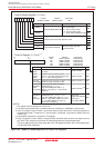
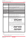
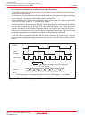
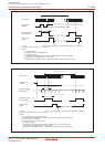
The counter is initialized at the next count timing after recognizing Z-phase input. Figure 12.10 shows
the relationship between the two-phase pulse (A phase and B phase) and the Z-phase.
If timer A3 overflow or underflow coincides with the counter initialization by Z-phase input, a timer A3
interrupt request is generated twice in succession. Do not use the timer A3 interrupt when using this
function.
m m+1 1 2 3 4 5
T3OUT
(A phase)
Count source
TA3IN
(B phase)
Timer A3
ZP
(1)
Input equal to or greater than one clock cycle
of count source
NOTE:
1. This timing diagram is for the case where the POL bit in the INT2IC register = 1 (rising edge).
Figure 12.10 Two-phase Pulse (A phase and B phase) and Z Phase