


Rev.1.10 Jul 01, 2005 page 245 of 318
REJ09B0124-0110
M16C/6N Group (M16C/6NK, M16C/6NM) 20. Flash Memory Version
Under development
This document is under development and its contents are subject to change.
20.3.3.1 FMR00 Bit
This bit indicates the flash memory operating status. It is set to “0” while the program, block erase, erase
all unlocked block, lock bit program, or read lock bit status command is being executed; otherwise, it is
set to “1”.
20.3.3.2 FMR01 Bit
The microcomputer can accept commands when the FMR01 bit is set to “1” (CPU rewrite mode). Set the
FMR05 bit to “1” (user ROM area access) as well if in boot mode.
20.3.3.3 FMR02 Bit
The lock bit is disabled by setting the FMR02 bit to “1” (lock bit disabled). (Refer to 20.3.6 Data Protect
Function.) The lock bit is enabled by setting the FMR02 bit to “0” (lock bit enabled).
The FMR02 bit does not change the lock bit status but disables the lock bit function. If the block erase or
erase all unlocked block command is executed when the FMR02 bit is set to “1”, the lock bit status
changes “0” (locked) to “1” (unlocked) after command execution is completed.
20.3.3.4 FMSTP Bit
This bit resets the flash memory control circuits and minimizes power consumption in the flash memory.
Access to the flash memory is disabled when the FMSTP bit is set to “1”. Set the FMSTP bit by program
in a space other than the flash memory.
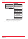
Set the FMSTP bit to “1” if one of the followings occurs:
• A flash memory access error occurs while erasing or programming in EW0 mode (FMR00 bit does not
switch back to “1” (ready))
• Low power dissipation mode or on-chip oscillator low power dissipation mode is entered
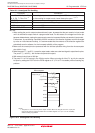
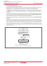
Figure 20.7 shows a flow chart illustrating how to start and stop the flash memory before and after
entering low power dissipation mode. Follow the procedure on this flow chart.
When entering stop or wait mode, the flash memory is automatically turned off. When exiting stop or wait
mode, the flash memory is turned back on. The FMR0 register does not need to be set.
20.3.3.5 FMR05 Bit
This bit selects the boot ROM or user ROM area in boot mode. Set to “0” to access (read) the boot ROM
area or to “1” (user ROM access) to access (read, write or erase) the user ROM area.
20.3.3.6 FMR06 Bit
This is a read-only bit indicating an auto program operation state. The FMR06 bit is set to “1” when a
program error occurs; otherwise, it is set to “0”. Refer to 20.3.8 Full Status Check.
20.3.3.7 FMR07 Bit
This is a read-only bit indicating the auto erase operation status. The FMR07 bit is set to “1” when an
erase error occurs; otherwise, it is set to “0”. For details, refer to 20.3.8 Full Status Check.
20.3.3.8 FMR11 Bit
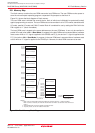
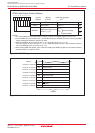
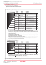
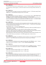
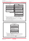
EW0 mode is entered by setting the FMR11 bit to “0” (EW0 mode).
EW1 mode is entered by setting the FMR11 bit to “1” (EW1 mode).
20.3.3.9 FMR16 Bit
This is a read-only bit indicating the execution result of the read lock bit status command. When the
block, where the read lock bit status command is executed, is locked, the FMR16 bit is set to “0”.
When the block, where the read lock bit status command is executed, is unlocked, the FMR16 bit is set
to “1”.
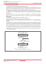
Figure 20.5 shows how to enter and exit EW0 mode. Figure 20.6 show how to enter and exit EW1 mode.