


Rev.1.10 Jul 01, 2005 page 234 of 318
REJ09B0124-0110
M16C/6N Group (M16C/6NK, M16C/6NM) 19. Programmable I/O Ports
Under development
This document is under development and its contents are subject to change.
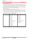
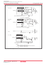
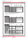
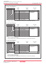
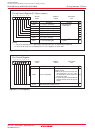
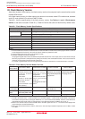
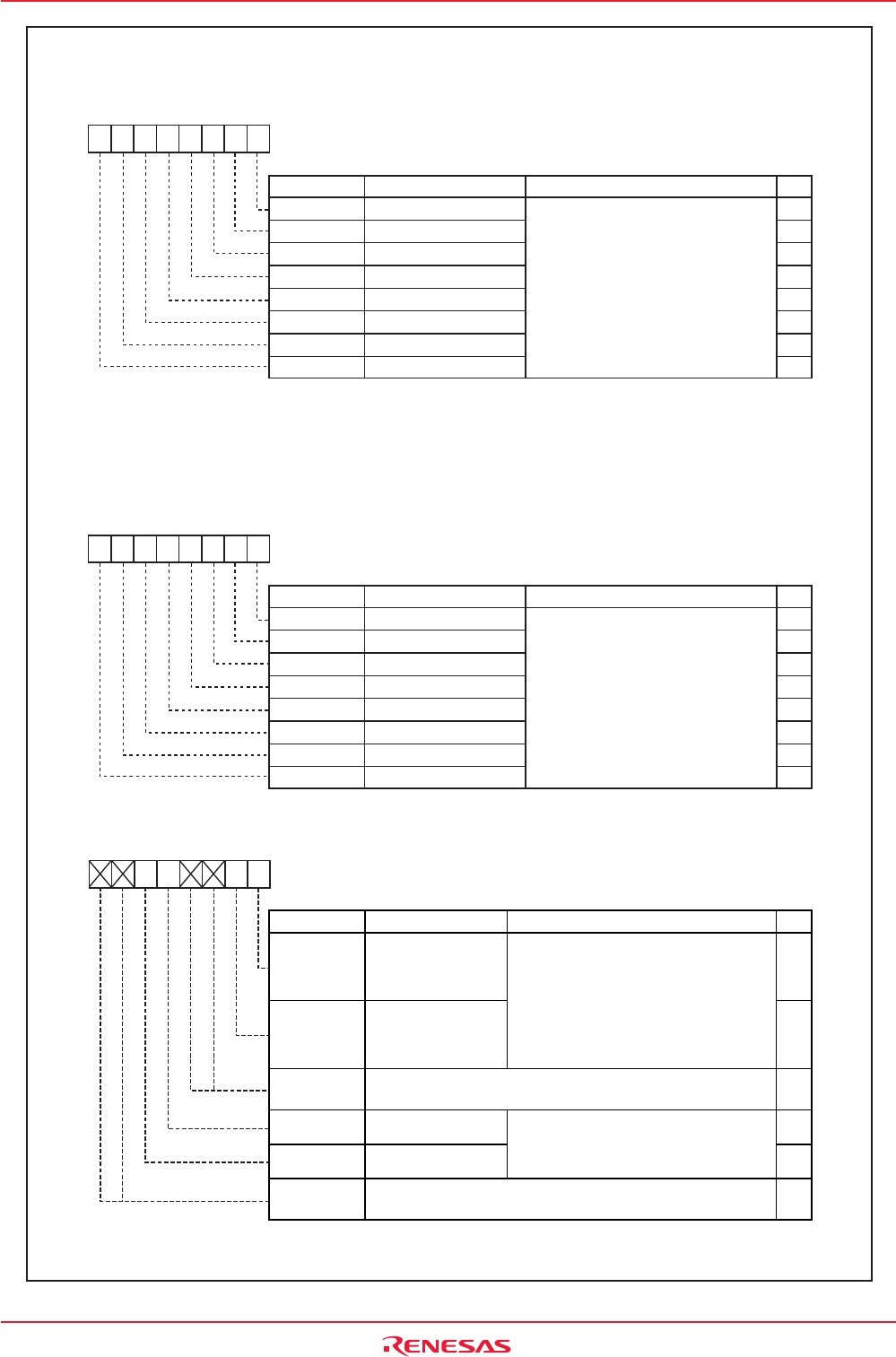
Figure19.8 P0 to P13 Registers and PC14 Register
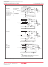
Port P8 Register
Bit nameBit symbol RW
b7 b6 b5 b4 b3 b2 b1 b0
P8
03F0h
Indeterminate
Symbol Address After Reset
P8_0
P8_1
Pi8_2
P8_3
P8_4
P8_5
P8_6
P8_7
Port P8 _0 Bit
Port P8 _1 Bit
Port P8 _2 Bit
Port P8 _3 Bit
Port P8 _4 Bit
Port P8 _5 Bit
Port P8 _6 Bit
Port P8 _7 Bit
The pin level on any I/O port which is set
for input mode can be read by reading
the corresponding bit in this register.
The pin level on any I/O port which is
set for output mode can be controlled
by writing to the corresponding bit in
this register. (Except for P8_5.)
0 : "L" level
1 : "H" level
RW
RW
RW
RW
RW
RO
RW
RW
Function
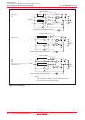
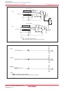
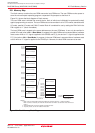
Port P14 Control Regisrer (128-pin version)
(1)
Address
03DEh
Symbol
PC14
After Reset
XX00XXXXb
RW
RW
RW
FunctionBit NameBit Symbol
P140 Port P14_0 Bit
P141 Port P14_1 Bit
The pin level on any I/O port which is set
for input mode can be read by reading the
corresponding bit in this register.
The pin level on any I/O port which isset for
output mode can be controlled by writing to
the corresponding bit in this register.
0 : "L" level
1 : "H" level
b7 b6 b5 b4 b3 b2 b1 b0
-
-
-
(b3-b2)
RW
RW
PD140
Port P14_0 Direction
Bit
PD141
Port P14_1 Direction
Bit
0 : Input mode
(Functions as an input port)
1 : Output mode
(Functions as an output port)
Nothing is assigned. When write, set to "0".
When read, their contents are indeterminate.
-
(b7-b6)
Nothing is assigned. When write, set to "0".
When read, their contents are indeterminate.
NOTE:
1. When using the port P14, set the PU37 bit in the PUR3 register to "1" (usable).
Bit NameBit Symbol RW
b7 b6 b5 b4 b3 b2 b1 b0
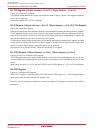
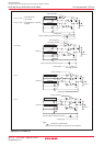
NOTES:
1. Since P7_1 and P9_1 are N channel open-drain ports, the data is high-impedance.
2. When using the ports P11 to P13, set the PU37 bit in the PUR3 register to "1" (usable).
If this bit is set to "0" (unusable), the P11 to P13 regisrers are set to "00h".
3. The P11 to P13 registers are only in the 128-pin version.
Pi_0
Pi_1
Pi_2
Pi_3
Pi_4
Pi_5
Pi_6
Pi_7
Port Pi_0 Bit
Port Pi_1 Bit
Port Pi_2 Bit
Port Pi_3 Bit
Port Pi_4 Bit
Port Pi_5 Bit
Port Pi_6 Bit
Port Pi_7 Bit
The pin level on any I/O port which is set
for input mode can be read by reading
the corresponding bit in this register.
The pin level on any I/O port which is
set for output mode can be controlled
by writing to the corresponding bit in
this register.
0 : "L" level
1 : "H" level
RW
RW
RW
RW
RW
RW
RW
RW
Function
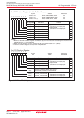
Port Pi Register (i = 0 to 7, 9 to 13)
(1) (2)
P0 to P3
P4 to P7
P9 to P12
(3)
P13
(3)
03E0h, 03E1h, 03E4h, 03E5h
03E8h, 03E9h, 03ECh, 03EDh
03F1h, 03F4h, 03F5h, 03F8h
03F9h
Indeterminate
Indeterminate
Indeterminate
Indeterminate
Symbol Address After Reset