


Rev.1.10 Jul 01, 2005 page 43 of 318
REJ09B0124-0110
M16C/6N Group (M16C/6NK, M16C/6NM) 7. Clock Generating Circuit
Under development
This document is under development and its contents are subject to change.
NOTE:
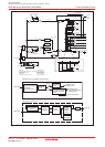
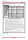
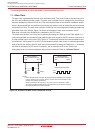
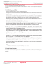
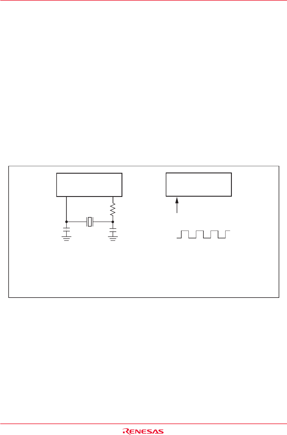
1.Place a damping resistor if required. The resistance will vary depending on the oscillator
and the oscillation drive capacity setting. Use the value recommended by each
oscillator the oscillator manufacturer.
When the oscillation drive capacity is set to low, check that oscillation is stable.
Also, place a feedback resistor between XIN and XOUT if the oscillator manufacturer
recommends
p
lacin
g
the resistor externall
y
.
Microcomputer
(Built-in feedback resistor)
Externally derived clock
Open
VCC
VSS
Microcomputer
(Built-in feedback resistor)
XIN XOUT XIN XOUT
Rd
(1)
CIN
COUT
Figure 7.9 Examples of Main Clock Connection Circuit
The following describes the clocks generated by the clock generating circuit.
7.1.1 Main Clock
The main clock is generated by the main clock oscillation circuit. This clock is used as the clock source for
the CPU and peripheral function clocks. The main clock oscillator circuit is configured by connecting a
resonator between the XIN and XOUT pins. The main clock oscillator circuit contains a feedback resistor,
which is disconnected from the oscillator circuit during stop mode in order to reduce the amount of power
consumed in the chip. The main clock oscillator circuit may also be configured by feeding an externally
generated clock to the XIN pin. Figure 7.9 shows the examples of main clock connection circuit.
After reset, the main clock divided by 8 is selected for the CPU clock.
The power consumption in the chip can be reduced by setting the CM05 bit in the CM0 register to “1”
(main clock oscillator circuit turned off) after switching the clock source for the CPU clock to a sub clock or
on-chip oscillator clock. In this case, XOUT goes “H”. Furthermore, because the internal feedback resis-
tor remains on, XIN is pulled “H” to XOUT via the feedback resistor. Note, that if an externally generated
clock is fed into the XIN pin, the main clock cannot be turned off by setting the CM05 bit to “1” unless the
sub clock is selected as a CPU clock. If necessary, use an external circuit to turn off the clock.
During stop mode, all clocks including the main clock are turned off. Refer to 7.4 Power Control.