


Rev.1.10 Jul 01, 2005 page 134 of 318
REJ09B0124-0110
M16C/6N Group (M16C/6NK, M16C/6NM) 14. Serial I/O
Under development
This document is under development and its contents are subject to change.
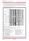
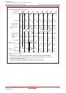
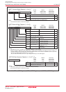
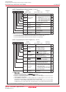
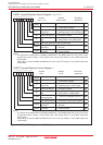
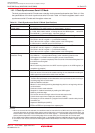
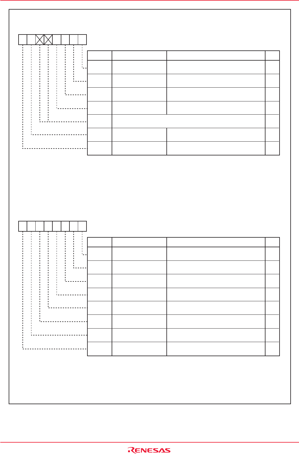
Figure 14.7 U0C1, U1C1 Registers and U2C1 Register
b7 b6 b5 b4 b3 b2 b1 b0
Function
UARTj Transmit/Receive Control Register 1 (j = 0, 1)
Bit Name
Bit
Symbol
Symbol Address After Reset
U0C1, U1C1 03A5h, 03ADh 00XX0010b
RW
TE
TI
RE
Transmit Buffer
Empty Flag
Receive Enable Bit
Transmit Enable Bit
RI
Receive Complete
Flag
Nothing is assigned. When write, set to "0".
When read, their contents are indeterminate.
0 : Transmission disabled
1 : Transmission enabled
0 : Data present in the UjTB register
1 : No data present in the UjTB register
0 : Reception disabled
1 : Reception enabled
0 : No data present in the UjRB register
1 : Data present in the UjRB register
-
(b5-b4)
RO
RW
RW
RO
-
Error Signal Output
Enable Bit
UjERE
0 : Output disabled
1 : Output enabled
RW
Data Logic
Select Bit
(1)
UjLCH
0 : No reverse
1 : Reverse
RW
b7 b6 b5 b4 b3 b2 b1 b0
Function
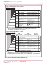
UART2 Transmit/Receive Control Register 1
Bit Name
Bit
Symbol
Symbol Address After Reset
U2C1 01FDh 00000010b
RW
TE
TI
RE
Transmit Buffer
Empty Flag
Receive Enable Bit
Transmit Enable Bit
RI
Receive Complete
Flag
0 : Transmission disabled
1 : Transmission enabled
0 : Data present in U2TB register
1 :
No data present in U2TB register
0 : Reception disabled
1 : Reception enabled
0 :
No data present in U2RB register
1 : Data present in U2RB register
RO
RW
RW
RO
Error Signal Output
Enable Bit
U2ERE
0 : Output disabled
1 : Output enabled
RW
Data Logic
Select Bit
(1)
U2LCH
0 : No reverse
1 : Reverse
RW
UART2 Continuous
Receive Mode Enable Bit
U2RRM
0 : Continuous receive mode disabled
1 : Continuous receive mode enabled
RW
UART2 Transmit Interrupt
Cause Select Bit
U2IRS
0 : Transmit buffer empty (TI bit = 1)
1 : Transmit is completed
(TXEPT bit = 1)
RW
NOTE:
1. The UjLCH bit is enabled when the SMD2 to SMD0 bits in the UjMR register are set to "001b" (clock
synchronous serial I/O mode), "100b" (UART mode, 7-bit transfer data) or "101b" (UART mode, 8-bit
transfer data).
Set this bit to "0" when the SMD2 to SMD0 bits are set to "010b" (I
2
C mode) or "110b" (UART mode, 9-bit
transfer data).
NOTE:
1. The U2LCH bit is enabled when the SMD2 to SMD0 bits in the U2MR register are set to "001b" (clock
synchronous serial I/O mode), "100b" (UART mode, 7-bit transfer data) or "101b" (UART mode, 8-bit
transfer data).
Set this bit to "0" when the SMD2 to SMD0 bits are set to "010b" (I
2
C mode) or "110b" (UART mode, 9-bit
transfer data) .