


Rev.1.10 Jul 01, 2005 page 226 of 318
REJ09B0124-0110
M16C/6N Group (M16C/6NK, M16C/6NM) 19. Programmable I/O Ports
Under development
This document is under development and its contents are subject to change.
19. Programmable I/O Ports
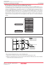
The programmable input/output ports (hereafter referred to simply as I/O ports) consist of 87 lines P0 to P10
in the 100-pin version and consist of 113 lines P0 to P14 in the 128-pin version. Each port can be set for input
or output every line by using a direction register, and can also be chosen to be or not be pulled high every 4
_______
lines. P8_5 is an input-only port and does not have a pull-up resistor. Port P8_5 shares the pin with NMI, so
______
that the NMI input level can be read from the P8_5 bit in the P8 register.
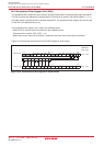
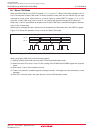
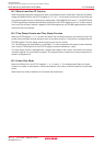
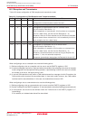
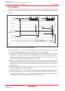
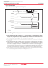
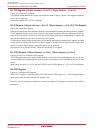
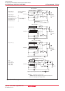
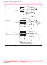
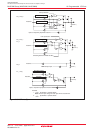
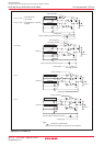
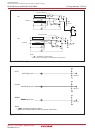
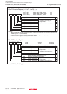
Table 19.1 lists the number of pins of the I/O ports of each package. Figures 19.1 to 19.5 show the I/O ports.
Figure19.6 shows the I/O pins.
Each pin functions as an I/O port or a peripheral function input/output pin.
For details on how to set peripheral functions, refer to each functional description in this manual. If any pin is
used as a peripheral function input, SI/O4 output or D/A converter output pin, set the direction bit for that pin
to “0” (input mode). Any pin used as an output pin for peripheral functions other than the SI/O4 and D/A
converter is directed for output no matter how the corresponding direction bit is set.
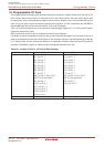
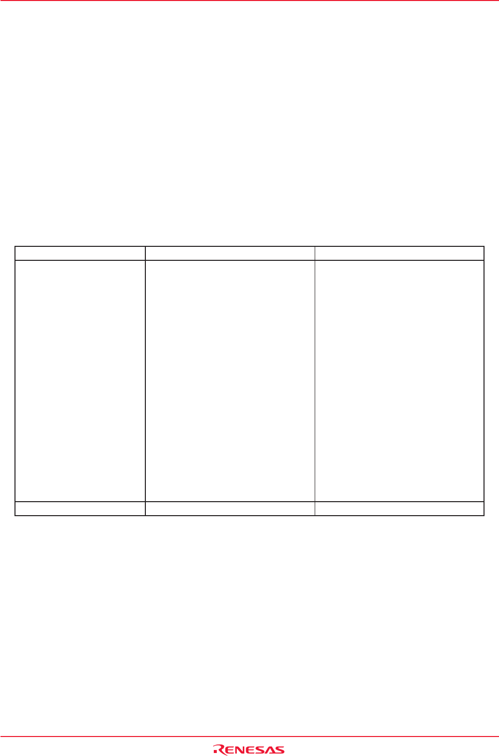
Table 19.1 Number of Pins of I/O Ports of Each Package
128-pin Version 100-pin Version
I/O Ports P0_0 to P0_7 P0_0 to P0_7
P1_0 to P1_7 P1_0 to P1_7
P2_0 to P2_7 P2_0 to P2_7
P3_0 to P3_7 P3_0 to P3_7
P4_0 to P4_7 P4_0 to P4_7
P5_0 to P5_7 P5_0 to P5_7
P6_0 to P6_7 P6_0 to P6_7
P7_0 to P7_7 P7_0 to P7_7
P8_0 to P8_4, P8_6, P8_7 P8_0 to P8_4, P8_6, P8_7
(P8_5 is an input port) (P8_5 is an input port)
P9_0 to P9_7 P9_0 to P9_7
P10_0 to P10_7 P10_0 to P10_7
P11_0 to P11_7
P12_0 to P12_7
P13_0 to P13_7
P14_0, P14_1
Total 113 pins 87 pins