


Rev.1.10 Jul 01, 2005 page 207 of 318
REJ09B0124-0110
M16C/6N Group (M16C/6NK, M16C/6NM) 18. CAN Module
Under development
This document is under development and its contents are subject to change.
18.4 CAN SFR Registers
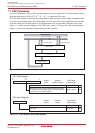
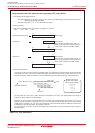
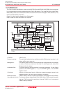
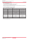
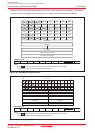
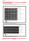
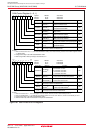
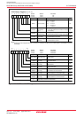
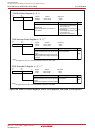
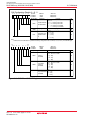
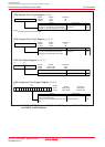
Figures 18.6 to 18.11 show the CAN SFR registers.
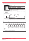
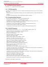
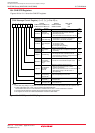
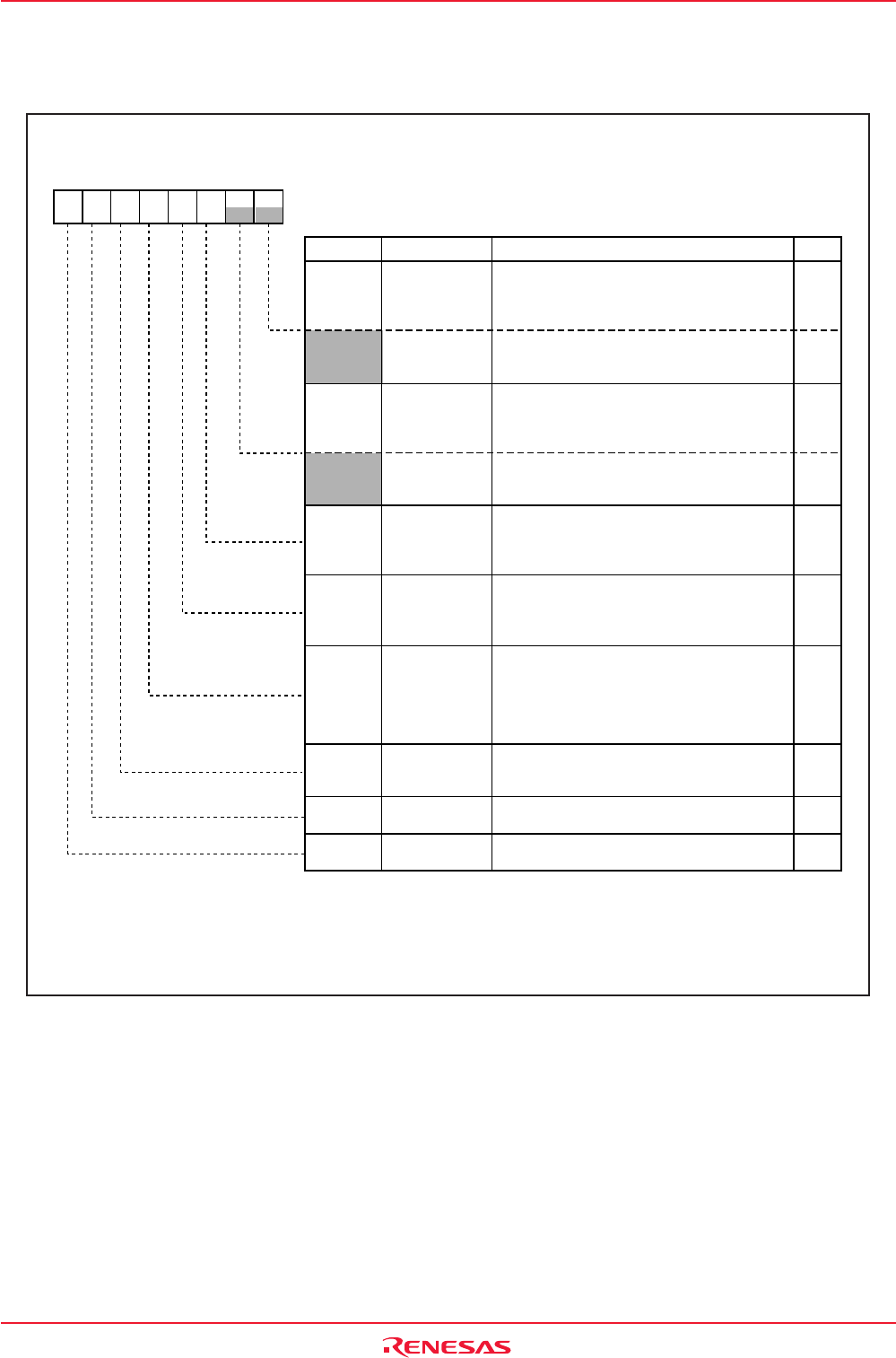
Figure 18.6 C0MCTLj and C1MCTLj Registers
b7 b6 b5 b4 b3 b2 b1 b0
Bit Symbol Bit Name Function
RW
RO
(1)
RO
(1)
RO
RO
RO
(1)
NewData
Successful
Reception Flag
SentData
Successful
Transmission Flag
When set to reception slot
0: The content of the slot is read or still under
processing by the CPU.
1 The CAN module has stored new data in the slot.
When set to reception slot
0: The message is valid.
1: The message is invalid.
(The message is being updated.)
When set to reception slot
0: No message has been overwritten in this slot.
1: This slot already contained a message, but it has
been overwritten by a new one.
When set to transmission slot
0: Transmission is not started or completed yet.
1: Transmission is successfully completed.
When set to transmission slot
0: Waiting for bus idle or completion of arbitration.
1: Transmitting
InvalData
TrmActive
"Under Reception"
Flag
"Under
Transmission"
Flag
MsgLost Overwrite Flag
Remote Frame
Transmission/
Reception Status
Flag
(2)
0: Data frame transmission/reception status
1: Remote frame transmission/reception status
RemActive
RspLock
Auto Response
Lock Mode
Select Bit
Remote Frame
Corresponding
Slot Select Bit
When set to reception remote frame slot
0: After a remote frame is received, it will be
answered automatically.
1: After a remote frame is received, no transmission
will be started as long as this bit is set to "1".
(Not responding)
0: Slot not corresponding to remote frame
1: Slot corresponding to remote frame
Remote
0: Not reception slot
1: Reception slot
RecReq
Reception Slot
Request Bit
(3)
0: Not transmission slot
1: Transmission slot
TrmReq
Transmission
Slot Request Bit
(3)
NOTES:
1. As for write, only writing "0" is possible. The value of each bit is written when the CAN module enters the respective state.
2. In Basic CAN mode, slots 14 and 15 serve as data format identification flag.
The RemActive bit is set to "0" if the data frame is received and it is set to "1" if the remote frame is received.
3. One slot cannot be defined as reception slot and transmission slot at the same time.
4. This register can not be set in CAN reset/initialization mode of the CAN module.
CANi Message Control Register j (i = 0, 1) ( j = 0 to 15)
(4)
Symbol
C0MCTL0 to C0MCTL15
C1MCTL0 to C1MCTL15
0200h to 020Fh
0220h to 022Fh
00h
00h
After Reset
Address
RW
RW
RW
RW
RW