


Rev.1.10 Jul 01, 2005 page 109 of 318
REJ09B0124-0110
M16C/6N Group (M16C/6NK, M16C/6NM) 12. Timers
Under development
This document is under development and its contents are subject to change.
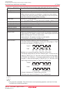
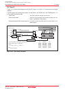
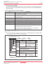
12.2 Timer B
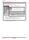
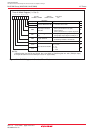
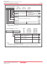
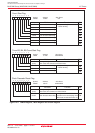
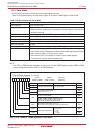
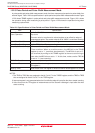
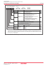
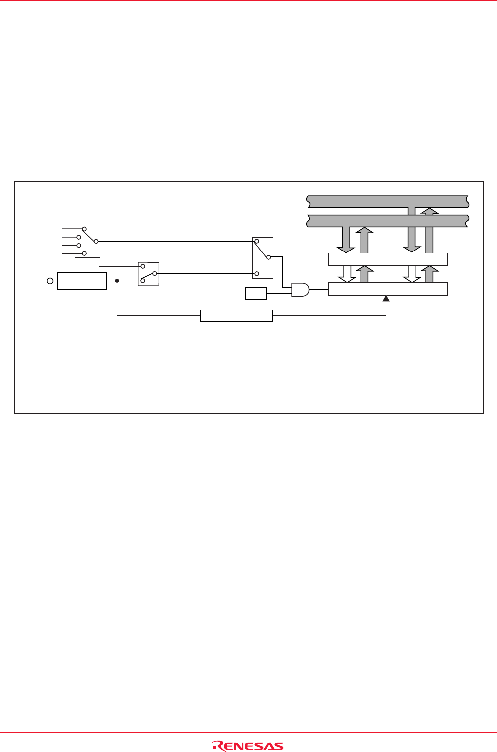
Figure 12.15 shows a block diagram of the timer B. Figures 12.16 and 12.17 show the timer B-related
registers.
Timer B supports the following three modes. Use the TMOD1 and TMOD0 bits in the TBiMR register (i = 0
to 5) to select the desired mode.
• Timer mode : The timer counts an internal count source.
• Event counter mode : The timer counts pulses from an external device or over
flows or underflows of other timers.
• Pulse period/pulse width measuring mode : The timer measures pulse period or pulse width of an
external signal.
TCK1 to TCK0, TMOD1 to TMOD0: Bits in TBiMR register
TBiS: Bit in TABSR register or TBSR register
i = 0 to 5
j
= i - 1 except j = 2 when i = 0, j = 5 when i = 3
NOTE:
1.Overflow or underflow
00
01
10
11
TCK1 to TCK0
Select clock source
TBiIN
TBj overflow
(1)
f1 or f2
f8
f32
fC32
00: Timer
10:
Pulse period measurement mode,
pulse width measurement mode
01: Event counter
TMOD1 to TMOD0
TCK1
1
0
Polarity Switching
and Edge Pulse
TBiS
High-order Bits of Data Bus
Low-order Bits of Data Bus
Reload Register
Counter
TBi Addresses TBj
Timer B0 0391h-0390h Timer B2
Timer B1 0393h-0392h Timer B0
Timer B2 0395h- 0394h Timer B1
Timer B3 01D1h-01D0h Timer B5
Timer B4 01D3h-01D2h Timer B3
Timer B5 01D5h-01D4h Timer B4
Counter Reset Circuit
Low-order
8 bits
High-order
8 bits
Figure 12.15 Timer B Block Diagram