


Rev.1.10 Jul 01, 2005 page 29 of 318
REJ09B0124-0110
M16C/6N Group (M16C/6NK, M16C/6NM) 5. Reset
Under development
This document is under development and its contents are subject to change.
5. Reset
Hardware reset, software reset, watchdog timer reset and oscillation stop detection reset are available to
reset the microcomputer.
5.1 Hardware Reset
____________
The microcomputer resets pins, the CPU and SFR by setting the RESET pin. If the supply voltage meets
the recommended operating conditions, the microcomputer resets all pins when an “L” signal is applied to
___________ ____________
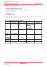
the RESET pin (see Table 5.1 Pin Status When RESET Pin Level is “L”). The oscillation circuit is also
reset and the main clock starts oscillation. The microcomputer resets the CPU and SFR when the signal
____________
applied to the RESET pin changes low (“L”) to high (“H”). The microcomputer executes the program in an
address indicated by the reset vector. The internal RAM is not reset. When an “L” signal is applied to the
____________
RESET pin while writing data to the internal RAM, the internal RAM is in an indeterminate state.
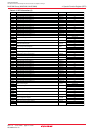
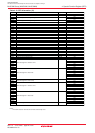
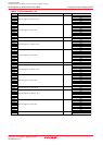
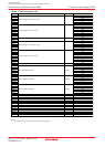
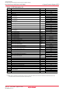
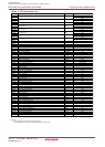
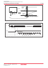
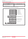
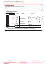
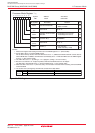
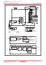
Figure 5.1 shows an example of the reset circuit. Figure 5.2 shows a reset sequence. Table 5.1 lists pin
____________
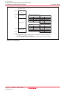
states while the RESET pin is held low (“L”). Figure 5.3 shows CPU register states after reset. Refer to 4.
SFR for SFR states after reset.
5.1.1 Reset on a Stable Supply Voltage
____________
(1) Apply “L” to the RESET pin
(2) Apply 20 or more clock cycles to the XIN pin
____________
(3) Apply “H” to the RESET pin
5.1.2 Power-on Reset
____________
(1) Apply “L” to the RESET pin
(2) Raise the supply voltage to the recommended operating level
(3) Insert td(P-R) ms as wait time for the internal voltage to stabilize
(4) Apply 20 or more clock cycles to the XIN pin
____________
(5) Apply “H” to the RESET pin
5.2 Software Reset
The microcomputer resets pins, the CPU and SFR when the PM03 bit in the PM0 register is set to “1”
(microcomputer reset). Then the microcomputer executes the program in an address determined by the reset vector.
Set the PM03 bit to “1” while the main clock is selected as the CPU clock and the main clock oscillation is stable.
In the software reset, the microcomputer does not reset a part of the SFR. Refer to 4. SFR for details.
5.3 Watchdog Timer Reset
The microcomputer resets pins, the CPU and SFR when the PM12 bit in the PM1 register is set to “1” (reset
when watchdog timer underflows) and the watchdog timer underflows. Then the microcomputer executes
the program in an address determined by the reset vector.
In the watchdog timer reset, the microcomputer does not reset a part of the SFR. Refer to 4. SFR for details.
5.4 Oscillation Stop Detection Reset
The microcomputer resets and stops pins, the CPU and SFR when the CM27 bit in the CM2 register is “0”
(reset at oscillation stop, re-oscillation detection), if it detects main clock oscillation circuit stop. Refer to 7.5
Oscillation Stop and Re-Oscillation Detection Function for details.
In the oscillation stop detection reset, the microcomputer does not reset a part of the SFR. Refer to 4. SFR
for details.