


Rev.1.10 Jul 01, 2005 page 122 of 318
REJ09B0124-0110
M16C/6N Group (M16C/6NK, M16C/6NM) 13. Three-Phase Motor Control Timer Function
Under development
This document is under development and its contents are subject to change.
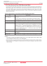
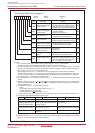
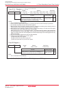
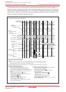
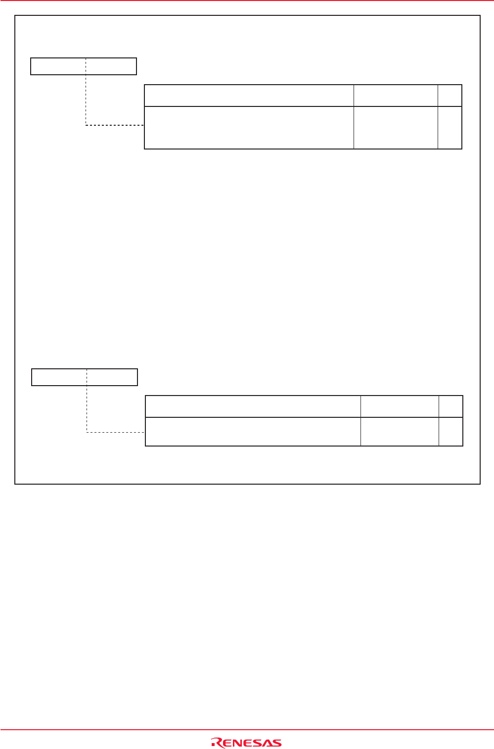
Figure 13.5 TA1, TA2, TA4, TA11, TA21 and TA41 Registers, and TB2 Register
Timer Ai, Ai-1 Register (i = 1, 2, 4)
(1) (2) (3) (4) (5) (6)
Symbol Address After Reset
TA1, TA2, TA4
0389h - 0388h, 038Bh - 038Ah, 038Fh - 038Eh
Indeterminate
TA11, TA21, TA41
(7)
01C3h - 01C2h, 01C5h - 01C4h, 01C7h - 01C6h
Indeterminate
RW
WO
Function
b0b8
Setting Range
0000h to FFFFh
b15 b7
If setting value is n, the timer stops when the nth
count
source is counted
after a start trigger is generated
.
Positive phase changes to negative phase, and vice
versa, when the timers A1, A2 and A4 stop.
NOTES:
1. Use a 16-bit data for read and write.
2. If the TAi or TAi1 register is set to "0000h", no counters start and no timer Ai interrupt is generated.
3. Use the MOV instruction to set the TAi and TAi1 registers.
4. When the INV15 bit in the INVC1 register is set to "0" (dead timer enabled), phase switches from an
inactive level to an active level when the dead time timer stops.
5. When the INV11 bit in the INVC1 register is set to "0" (three-phase mode 0), the value of the TAi register
is transferred to the reload register by a timer Ai start trigger.
When the INV11 bit is set to "1" (three-phase mode 1), the value of the TAi1 register is first transferred to
the reload register by a timer Ai start trigger. Then, the value of the TAi register is transferred by the next
trigger. The values of the TAi1 and TAi registers are transferred alternately to the reload register with every
timer Ai start trigger.
6. Do not write to these registers when the timer B2 underflows.
7. Follow the procedure below to set the TAi1 register.
(a) Write value to the TAi1 register,
(b) Wait one timer Ai count source cycle, and
(c) Write the same value as (a) to the TAi1 register.
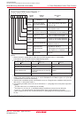
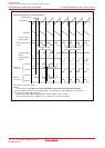
Timer B2 Register
(1)
Symbol Address After Reset
TB2 0395h - 0394h Indeterminate
RW
RW
Function
b0b8
Setting Range
If setting value is
n
, count source is divided by
n
+1.
The timers A1, A2 and A4 start every time an underflow occurs.
0000h to FFFFh
NOTE:
1. Use a 16-bit data for read and write.
b15 b7