


Rev.1.10 Jul 01, 2005 page 64 of 318
REJ09B0124-0110
M16C/6N Group (M16C/6NK, M16C/6NM) 9. Interrupt
Under development
This document is under development and its contents are subject to change.
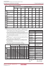
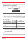
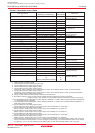
Table 9.2 Relocatable Vector Tables
0
1
2
3
4
5
6
7
8
9
10
11
12
13
14
15
16
17
18
19
20
21
22
23
24
25
26
27
28
29
30
31
32
to
63
BRK Instruction
(2)
CAN0/1 Wake-up
(10)
CAN0 Successful Reception
CAN0 Successful Transmission
________
INT3
Timer B5, SI/O5
(12)
Timer B4, UART1 Bus Collision Detection
(3) (9)
Timer B3, UART0 Bus Collision Detection
(4) (9)
________
CAN1 Successful Reception,SIO4, INT5
(5)
________
CAN1 Successful Transmission, SIO3, INT4
(6)
UART2 Bus Collision Detection
(9)
DMA0
DMA1
CAN0/1 Error
(11) (17)
A/D, Key Input
(7) (17)
UART2 Transmission, NACK2
(8)
UART2 Reception, ACK2
(8)
UART0 Transmission, NACK0
(8)
UART0 Reception, ACK0
(8)
UART1 Transmission, NACK1
(8)
UART1 Reception, ACK1
(8)
Timer A0
Timer A1
________
Timer A2, INT7
(13)
________
Timer A3, INT6
(14)
Timer A4
Timer B0, SI/O6
(15)
________
Timer B1, INT8
(16)
Timer B2
________
INT0
________
INT1
________
INT2
INT Instruction Interrupt
(2)
+0 to +3 (0000h to 0003h)
+4 to +7 (0004h to 0007h)
+8 to +11 (0008h to 000Bh)
+12 to +15 (000Ch to 000Fh)
+16 to +19 (0010h to 0013h)
+20 to +23 (0014h to 0017h)
+24 to +27 (0018h to 001Bh)
+28 to +31 (001Ch to 001Fh)
+32 to +35 (0020h to 0023h)
+36 to +39 (0024h to 0027h)
+40 to +43 (0028h to 002Bh)
+44 to +47 (002Ch to 002Fh)
+48 to +51 (0030h to 0033h)
+52 to +55 (0034h to 0037h)
+56 to +59 (0038h to 003Bh)
+60 to +63 (003Ch to 003Fh)
+64 to +67 (0040h to 0043h)
+68 to +71 (0044h to 0047h)
+72 to +75 (0048h to 004Bh)
+76 to +79 (004Ch to 004Fh)
+80 to +83 (0050h to 0053h)
+84 to +87 (0054h to 0057h)
+88 to +91 (0058h to 005Bh)
+92 to +95 (005Ch to 005Fh)
+96 to +99 (0060h to 0063h)
+100 to +103 (0064h to 0067h)
+104 to +107 (0068h to 006Bh)
+108 to +111 (006Ch to 006Fh)
+112 to +115 (0070h to 0073h)
+116 to +119 (0074h to 0077h)
+120 to +123 (0078h to 007Bh)
+124 to +127 (007Ch to 007Fh)
+128 to +131 (0080h to 0083h)
to
+252 to + 255 (00FCh to 00FFh)
Software
Interrupt Number
M16C/60, M16C/20 Series
Software Manual
18. CAN Module
______
9.6 INT Interrupt
12. Timers
14. Serial I/O
18. CAN Module, 14. Serial I/O,
______
9.6 INT Interrupt
14. Serial I/O
11. DMAC
18. CAN Module
15. A/D Convertor, 9.8 Key Input Interrupt
14. Serial I/O
12. Timers
12. Timers
______
9.6 INT Interrupt
12. Timers
12. Timers, 14. Serial I/O
______
12. Timers, 9.6 INT Interrupt
12. Timers
______
9.6 INT Interrupt
M16C/60, M16C/20 Series
Software Manual
Interrupt Source
Vector Address
(1)
Address (L) to Address (H)
Reference
NOTES:
1. Address relative to address in INTB.
2. These interrupts cannot be disabled using the I flag.
3. Use the IFSR07 bit in the IFSR0 register to select.
4. Use the IFSR06 bit in the IFSR0 register to select.
5. Use the IFSR17 bit in the IFSR1 register to select.
Furthermore, use the IFSR03 bit in the IFSR0 register to select, when selecting SI/O4 or CAN1 successful reception.
6. Use the IFSR16 bit in the IFSR1 register to select.
Furthermore, use the IFSR00 bit in the IFSR0 register to select, when selecting SI/O3 or CAN1 successful transmission.
7. Use the IFSR01 bit in the IFSR0 register to select.
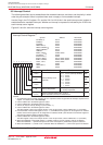
8. During I
2
C mode, NACK and ACK interrupts comprise the interrupt source.
9. Bus collision detection: During IE mode, this bus collision detection constitutes the cause of an interrupt.
During I
2
C mode, a start condition or a stop condition detection constitutes the cause of an interrupt.
10. Use the IFSR02 bit in the IFSR0 register to select. When the IFSR02 bit = 0, CAN0/1 wake-up is selected. When the IFSR02 bit
= 1, CAN0 wake-up/error is selected.
11. Use the IFSR02 bit in the IFSR0 register to select. When the IFSR02 bit = 0, CAN0/1 error is selected. When the IFSR02 bit = 1,
CAN1 wake-up/error is selected.
12. Use the IFSR04 bit in the IFSR0 register to select.
SI/O5 is only in the 128-pin version. In the 100-pin version, set the IFSR04 bit to “0” (Timer B5).
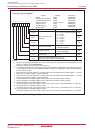
13. Use the IFSR20 bit in the IFSR2 register to select.
________
INT7 is only in the 128-pin version. In the 100-pin version, set the IFSR20 bit to “0” (Timer A2).
14. Use the IFSR21 bit in the IFSR2 register to select.
________
INT6 is only in the 128-pin version. In the 100-pin version, set the IFSR21 bit to “0” (Timer A3).
15. Use the IFSR05 bit in the IFSR0 register to select.
SI/O6 is only in the 128-pin version. In the 100-pin version, set the IFSR05 bit to “0” (Timer B0).
16. Use the IFSR22 bit in the IFSR2 register to select.
________
INT8 is only in the 128-pin version. In the 100-pin version, set the IFSR22 bit to “0” (Timer B1).
17. If the PCLK6 bit in the PCLKR register is set to “1”, software interrupt number 13 can be changed to CAN0/1 error or key input
interupt, and software interrupt number 14 can be changed to A/D interrupt. (The software interrupt number of key input is
changed from 14 to 13.) Use the IFSR26 bit in the IFSR2 register to select when selecting CAN0/1 error or key input.