


Rev.1.10 Jul 01, 2005 page 224 of 318
REJ09B0124-0110
M16C/6N Group (M16C/6NK, M16C/6NM) 18. CAN Module
Under development
This document is under development and its contents are subject to change.
18.15.2 Transmission
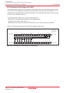
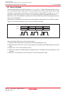
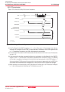
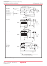
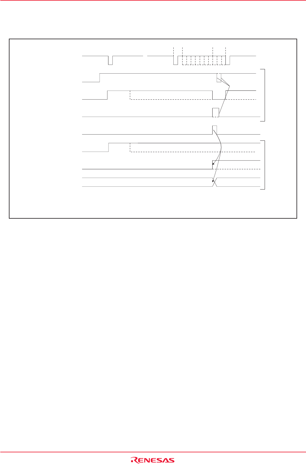
Figure 18.21 shows the timing of the transmit sequence.
CTX
TrmReq bit
TrmActive bit
CANi Successful
Transmission Interrupt
TrmState bit
TrmSucc bit
MBOX bit
SentData bit
Transmission slot No.
CiMCTLj register
CiSTR register
(1)
(2)
(2)
(1)
(1)
(3)
(4)
(3)
(3)
i = 0, 1
j = 0 to 15
SOF SOFEOF IFSACK
Figure 18.21 Timing of Transmit Sequence
(1) If the TrmReq bit in the CiMCTLj register (i = 0, 1, j = 0 to 15) is set to “1” (Transmission slot) in the bus
idle state, the TrmActive bit in the CiMCTLj register and the TrmState bit in the CiSTR register are set
to “1” (Transmitting/Transmitter), and CAN module starts the transmission.
(2) If the arbitration is lost after the CAN module starts the transmission, the TrmActive and TrmState bits
are set to “0”.
(3) If the transmission has been successful without lost in arbitration, the SentData bit in the CiMCTLj
register is set to “1” (Transmission is successfully completed) and TrmActive bit is set to “0” (Waiting
for bus idle or completion of arbitration). And when the interrupt enable bits in the CiICR register = 1
(Interrupt enabled), CANi successful transmission interrupt request is generated and the MBOX (the
slot number which transmitted the message) and TrmSucc bit in the CiSTR register are changed.
(4) When starting the next transmission, set the SentData and TrmReq bits to “0”. And set the TrmReq bit
to “1” after checking that the SentData and TrmReq bits are set to “0”.