


Rev.1.10 Jul 01, 2005 page 73 of 318
REJ09B0124-0110
M16C/6N Group (M16C/6NK, M16C/6NM) 9. Interrupt
Under development
This document is under development and its contents are subject to change.
______
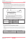
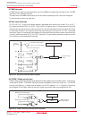
9.6 INT Interrupt
_______
INTi interrupt (i = 0 to 8)
(1)
is triggered by the edges of external inputs. The edge polarity is selected using
the IFSR10 to IFSR15 bits in the IFSR1 register and the IFSR23 to IFSR25 bits in the IFSR2 register.
________
INT4 share the interrupt vector and interrupt control register with CAN1 successful transmission and SI/O3,
________ ________ ________
INT5 share with CAN1 successful reception and SI/O4, INT6 share with Timer A3, INT7 share with Timer
________ ________ ________
A2, INT8 share with Timer B1. To use the INT4 to INT8 interrupts
(1)
, set the each bits as follows.
________ ________
• To use the INT4 interrupt: Set the IFSR16 bit in the IFSR1 register to “1” (INT4).
________ ________
• To use the INT5 interrupt: Set the IFSR17 bit in the IFSR1 register to “1” (INT5).
________ ________
• To use the INT6 interrupt: Set the IFSR21 bit in the IFSR2 register to “1” (INT6).
(1)
________ ________
• To use the INT7 interrupt: Set the IFSR20 bit in the IFSR2 register to “1” (INT7).
(1)
________ ________
• To use the INT8 interrupt: Set the IFSR22 bit in the IFSR2 register to “1” (INT8).
(1)
After modifying the IFSR16, IFSR17, IFSR20, IFSR21 and IFSR22 bits, set the corresponding IR bit to “0”
(interrupt not requested) before enabling the interrupt.
NOTE:
________ ________
1. INT6 to INT8 interrupts are only in the 128-pin version.
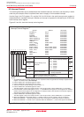
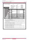
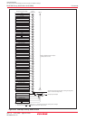
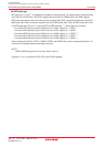
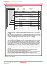
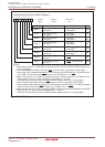
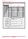
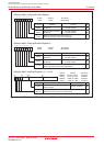
Figures 9.11 to 9.13 show the IFSR0, IFSR1 and IFSR2 registers.