


Rev.1.10 Jul 01, 2005 page 298 of 318
REJ09B0124-0110
M16C/6N Group (M16C/6NK, M16C/6NM) 22. Usage Precaution
Under development
This document is under development and its contents are subject to change.
22.11.2 Special Modes
22.11.2.1 Special Mode 1 (I
2
C Mode)
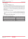
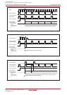
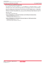
When generating start, stop and restart conditions, set the STSPSEL bit in the UiSMR4 register to “0”
(start and stop conditions not output) and wait for more than half cycle of the transfer clock before setting
each condition generate bit (STAREQ, RSTAREQ and STPREQ bits) from “0” (clear) to “1” (start).
22.11.2.2 Special Mode 2
_______
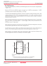
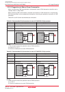
If a low-level signal is applied to the NMI pin when the IVPCR1 bit in the TB2SC register = 1 (three-phase
_______ _________
output forcible cutoff by input on NMI pin enabled), the RTS2 and CLK2 pins go to a high-impedance state.
22.11.2.3 Special Mode 4 (SIM Mode)
A transmit interrupt request is generated by setting the U2IRS bit in the U2C1 register to “1” (transmission
complete) and U2ERE bit in the U2C1 register to “1” (error signal output) after reset. Therefore, when
using SIM mode, be sure to set the IR bit to “0” (no interrupt request) after setting these bits.