


Rev.1.10 Jul 01, 2005 page 78 of 318
REJ09B0124-0110
M16C/6N Group (M16C/6NK, M16C/6NM) 9. Interrupt
Under development
This document is under development and its contents are subject to change.
9.10 Address Match Interrupt
An address match interrupt request is generated immediately before executing the instruction at the ad-
dress indicated by the RMADi register (i = 0 to 3). Set the start address of any instruction in the RMADi
register. Use the AIER0 and AIER1 bits in the AIER register and the AIER20 and AIER21 bits in the AIER2
register to enable or disable the interrupt. Note that the address match interrupt is unaffected by the I flag
and IPL. For address match interrupts, the value of the PC that is saved to the stack area varies depending
on the instruction being executed (refer to 9.5.7 Saving Registers). (The value of the PC that is saved to
the stack area is not the correct return address.) Therefore, follow one of the methods described below to
return from the address match interrupt.
• Rewrite the content of the stack and then use the REIT instruction to return.
• Restore the stack to its previous state before the interrupt request was accepted by using the POP or
similar other instruction and then use a jump instruction to return.
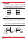
Table 9.6 shows the value of the PC that is saved to the stack area when an address match interrupt
request is accepted.
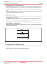
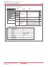
Table 9.7 shows the relationship between address match interrupt sources and associated registers.
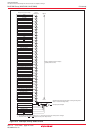
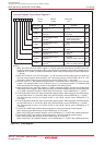
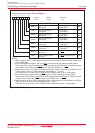
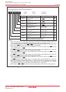
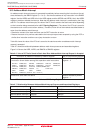
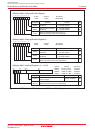
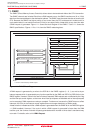
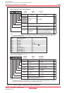
Figure 9.16 shows the AIER, AIER2, and RMAD0 to RMAD3 registers.
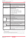
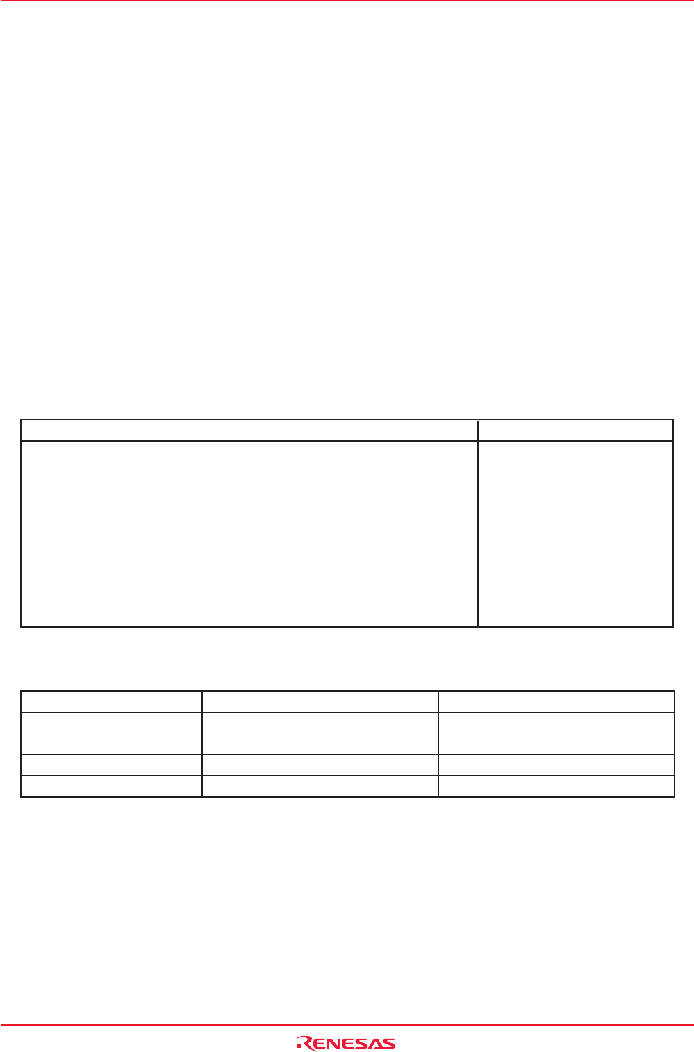
Table 9.6
Value of PC That is Saved to Stack Area When Address Match Interrupt Request is Accepted
Address Match Interrupt Sources
Address Match Interrupt Enable Bit Address Match Interrupt Register
Address Match Interrupt 0 AIER0 RMAD0
Address Match Interrupt 1 AIER1 RMAD1
Address Match Interrupt 2 AIER20 RMAD2
Address Match Interrupt 3 AIER21 RMAD3
Instruction at Address Indicated by RMADi Register
• 16-bit operation code
• Instruction shown below among 8-bit operation code instructions
ADD.B:S #IMM8,dest SUB.B:S #IMM8,dest AND.B:S #IMM8,dest
OR.B:S #IMM8,dest MOV.B:S #IMM8,dest STZ.B:S #IMM8,dest
STNZ.B:S #IMM8,dest STZX.B:S #IMM81,#IMM82,dest
CMP.B:S #IMM8,dest PUSHM src POPM dest
JMPS #IMM8 JSRS #IMM8
MOV.B:S #IMM,dest (However, dest = A0 or A1)
Instructions other than the above
Value of PC that is saved to stack area: Refer to 9.5.7 Saving Registers.
Table 9.7 Relationship Between Address Match Interrupt Sources and Associated Registers
Value of PC that is Saved to Stack Area
Address indicated by RMADi
register + 2
Address indicated by RMADi
register + 1