


Rev.1.10 Jul 01, 2005 page 185 of 318
REJ09B0124-0110
M16C/6N Group (M16C/6NK, M16C/6NM) 15. A/D Converter
Under development
This document is under development and its contents are subject to change.
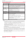
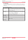
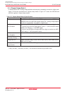
Item Specification
Function
T
he CH2 to CH0 bits in the ADCON0 register, the ADGSEL1 to ADGSEL0
bits in the ADCON2 register and the OPA1 to OPA0 bits in the ADCON1
register select a pin Analog voltage applied to the pin is converted to a
digital code once.
A/D Conversion • When the TRG bit in the ADCON0 register is “0” (software trigger)
Start Condition The ADST bit in the ADCON0 register is set to “1” (A/D conversion starts)
•
_____________
When the TRG bit is “1” (ADTRG trigger)
_____________
Input on the ADTRG pin changes state from high to low after the ADST
bit is set to “1” (A/D conversion starts)
A/D Conversion • Completion of A/D conversion (If a software trigger is selected, the ADST
Stop Condition bit is set to “0” (A/D conversion halted).)
• Set the ADST bit to “0”
Interrupt Request Completion of A/D conversion
Generation Timing
Analog Input Pin Select one pin from AN0 to AN7, AN0_0 to AN0_7, AN2_0 to AN2_7,
ANEX0 to ANEX1
Reading of Result of Read one of the AD0 to AD7 registers that corresponds to the selected pin
A/D Converter
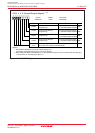
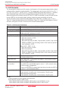
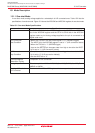
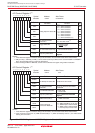
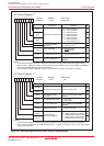
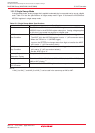
15.1 Mode Description
15.1.1 One-shot Mode
In one-shot mode, analog voltage applied to a selected pin is A/D converted once. Table 15.2 lists the
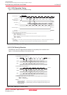
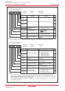
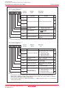
specifications of one-shot mode. Figure 15.4 shows the ADCON0 and ADCON1 registers in one-shot mode.
Table 15.2 One-shot Mode Specifications