


Rev.1.10 Jul 01, 2005 page 213 of 318
REJ09B0124-0110
M16C/6N Group (M16C/6NK, M16C/6NM) 18. CAN Module
Under development
This document is under development and its contents are subject to change.
18.5 Operational Modes
The CAN module has the following four operational modes.
• CAN Reset/Initialization Mode
• CAN Operation Mode
• CAN Sleep Mode
• CAN Interface Sleep Mode
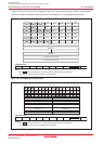
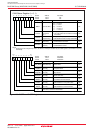
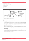
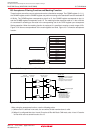
Figure 18.12 shows transition between operational modes.
Figure 18.12 Transition Between Operational Modes
18.5.1 CAN Reset/Initialization Mode
The CAN reset/initialization mode is activated upon MCU reset or by setting the Reset bit in the CiCTLR
register ( i = 0, 1) to “1”. If the Reset bit is set to “1”, check that the State_Reset bit in the CiSTR register is
set to “1”.
Entering the CAN reset/initialization mode initiates the following functions by the module:
• CAN communication is impossible.
• When the CAN reset/initialization mode is activated during an ongoing transmission in operation
mode, the module suspends the mode transition until completion of the transmission (successful,
arbitration loss, or error detection). Then, the State_Reset bit is set to “1”, and the CAN reset/initialization
mode is activated.
• The CiMCTLj (j = 0 to 15), CiSTR, CiICR, CiIDR, CiRECR, CiTECR and CiTSR registers are initialized.
All these registers are locked to prevent CPU modification.
• The CiCTLR, CiCONR, CiGMR, CiLMAR and CiLMBR registers and the CANi message box retain their
contents and are available for CPU access.
MCU Reset
CAN reset/initialization
mode
State_Reset = 1
CAN operation mode
State_Reset = 0
CAN sleep mode
CAN interface
sleep mode
Bus off state
State_BusOff = 1
Reset = 0
Sleep = 1
and
Reset = 0
Sleep = 0
and
Reset = 1
TEC > 255
Reset = 1
Reset = 1
CCLK3, CCLK7: Bits in CCLKR register
Reset, Sleep, RetBusOff: Bits in CiCTLR register ( i = 0, 1)
State_Reset, State_BusOff: Bits in CiSTR register
CCLK3 = 1 or
CCLK7 = 1
CCLK3 = 0 or
CCLK7 = 0
when 11 consecutive
recessive bits are
detected 128 times
or
RetBusOff = 1