


Rev.1.10 Jul 01, 2005 page 132 of 318
REJ09B0124-0110
M16C/6N Group (M16C/6NK, M16C/6NM) 14. Serial I/O
Under development
This document is under development and its contents are subject to change.
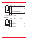
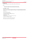
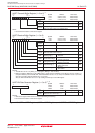
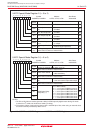
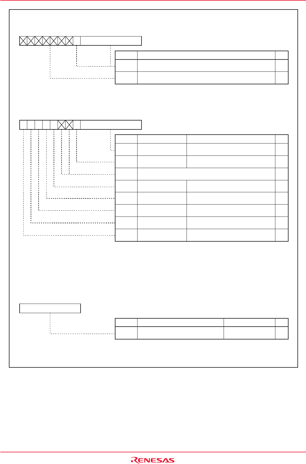
Figure 14.5 U0TB to U2TB Registers, U0RB to U2RB Registers, and U0BRG to U2BRG Registers
Nothing is assigned When write, set to "0".
When read, their contents are indeterminate.
-
(b15-b9)
-
(b8-b0)
b7 b0 b0b7
Function
UARTi Transmit Buffer Register (i = 0 to 2)
(1)
Bit
Symbol
Symbol Address After Reset
U0TB 03A3h to 03A2h
Indeterminate
U1TB 03ABh to 03AAh
Indeterminate
U2TB 01FBh to 01FAh
Indeterminate
RW
Transmit data
WO
-
NOTE:
1. Use the MOV instruction to write to this register.
(b15) (b8)
-
(b7-b0)
Assuming that set value = n, UiBRG
divides the count source by n + 1
00h to FFh
WO
b7 b0
Function Setting Range
UARTi Bit Rate Generator Register (i = 0 to 2)
(1) (2)
Bit
Symbol
Symbol Address After Reset
U0BRG 03A1h
Indeterminate
U1BRG 03A9h
Indeterminate
U2BRG 01F9h
Indeterminate
RW
NOTES:
1. Write to this register while serial I/O is neither transmitting nor receiving.
2. Use the MOV instruction to write to this register.
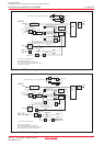
Nothing is assigned When write, set to "0".
When read, their contents are "0".
-
(b10-b9)
-
(b7-b0)
-
(b8)
b7 b0
(b15) (b8)
b7 b0
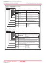
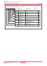
Function
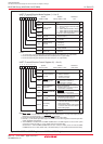
UARTi Receive Buffer Register (i = 0 to 2)
Bit Name
Bit
Symbol
Symbol Address After Reset
U0RB 03A7h to 03A6h
Indeterminate
U1RB 03AFh to 03AEh
Indeterminate
U2RB 01FFh to 01FEh
Indeterminate
RW
-
-
ABT
Arbitration Lost
Detecting Flag
(1)
Receive data (
D7 to D0)
Receive data (
D8)
0 : Not detected
1 : Detected
RO
RO
-
RW
Error Sum Flag
(2)
SUM
0 : No error
1 : Error found
RO
Parity Error Flag
(2)
PER
0 : No parity error
1 : Parity error found
RO
Framing Error Flag
(2)
FER
0 : No framing error
1 : Framing error found
RO
Overrun Error Flag
(2)
OER
0 : No overrun error
1 : Overrun error found
RO
NOTES:
1. The ABT bit is set to "0" by writing "0" in a program. (Writing "1" has no effect.)
2.When the SMD2 to SMD0 bits in the UiMR register = 000b (serial I/O disabled) or the RE bit in the UiC1 register = 0
(reception disabled), all of the SUM, PER, FER and OER bits are set to "0" (no error). The SUM bit is set to "0" (no error)
when all of the PER, FER and OER bits are = 0 (no error).
Also, the PER and FER bits are set to "0" by reading the lower byte of the UiRB register.