


Rev.1.10 Jul 01, 2005 page 159 of 318
REJ09B0124-0110
M16C/6N Group (M16C/6NK, M16C/6NM) 14. Serial I/O
Under development
This document is under development and its contents are subject to change.
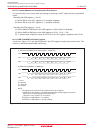
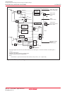
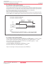
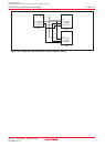
14.1.3.1 Detection of Start and Stop Condition
Whether a start or a stop condition has been detected is determined.
A start condition-detected interrupt request is generated when the SDAi pin changes state from high to
low while the SCLi pin is in the high state. A stop condition-detected interrupt request is generated when
the SDAi pin changes state from low to high while the SCLi pin is in the high state.
Figure 14.25 shows the detection of start and stop condition.
Because the start and stop condition-detected interrupts share the interrupt control register and vector,
check the BBS bit in the UiSMR register to determine which interrupt source is requesting the interrupt.
Figure 14.25 Detection of Start and Stop Condition
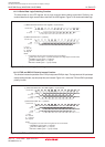
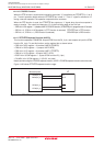
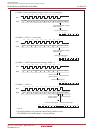
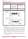
14.1.3.2 Output of Start and Stop Condition
A start condition is generated by setting the STAREQ bit in the UiSMR4 register (i = 0 to 2) to “1” (start).
A restart condition is generated by setting the RSTAREQ bit in the UiSMR4 register to “1” (start).
A stop condition is generated by setting the STPREQ bit in the UiSMR4 register to “1” (start).
The output procedure is described below.
(1) Set the STAREQ bit, RSTAREQ bit or STPREQ bit to “1” (start).
(2) Set the STSPSEL bit in the UiSMR4 register to “1” (output).
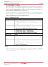
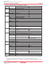
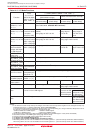
Table 14.13 and Figure 14.26 show the functions of the STSPSEL bit.
3 to 6 cycles < duration for setting-up
(1)
3 to 6 cycles < duration for holding
(1)
Duration for
setting-up
Duration for
holding
SCLi
SDAi
(Start condition)
SDA i
(Stop condition)
i = 0 to 2
NOTE:
1.When the PCLK1 bit in the PCLKR register = 1, this is the cycle number
of f1SIO, and when the PCLK1 bit = 0, this is the cycle number of f2SIO.