


Rev.1.10 Jul 01, 2005 page 203 of 318
REJ09B0124-0110
M16C/6N Group (M16C/6NK, M16C/6NM) 18. CAN Module
Under development
This document is under development and its contents are subject to change.
18.1 CAN Module-Related Registers
The CANi (i = 0, 1) module has the following registers.
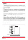
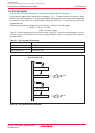
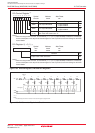
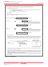
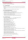
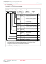
18.1.1 CAN Message Box
A CAN module is equipped with 16 slots (16 bytes or 8 words each). Slots 14 and 15 can be used as
Basic CAN.
• Priority of the slots: The smaller the number of the slot, the higher the priority, in both transmission and
reception.
• A program can define whether a slot is defined as transmitter or receiver.
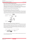
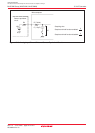
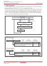
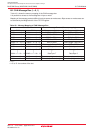
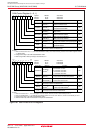
18.1.2 Acceptance Mask Registers
A CAN module is equipped with 3 masks for the acceptance filter.
• CANi global mask register (i = 0, 1) (CiGMR register: 6 bytes)
Configuration of the masking condition for acceptance filtering processing to slots 0 to 13
• CANi local mask A register (CiLMAR register: 6 bytes)
Configuration of the masking condition for acceptance filtering processing to slot 14
• CANi local mask B register (CiLMBR register: 6 bytes)
Configuration of the masking condition for acceptance filtering processing to slot 15
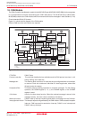
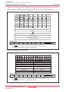
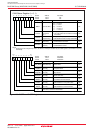
18.1.3 CAN SFR Registers
• CANi message control register j (i = 0, 1, j = 0 to 15) (CiMCTLj register: 8 bits ✕ 16)
Control of transmission and reception of a corresponding slot
• CANi control register (CiCTLR register: 16 bits)
Control of the CAN protocol
• CANi status register (CiSTR register: 16 bits)
Indication of the protocol status
• CANi slot status register (CiSSTR register: 16 bits)
Indication of the status of contents of each slot
• CANi interrupt control register (CiICR register: 16 bits)
Selection of “interrupt enabled or disabled” for each slot
• CANi extended ID register (CiIDR register: 16 bits)
Selection of ID format (standard or extended) for each slot
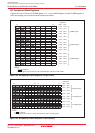
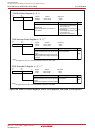
• CANi configuration register (CiCONR register: 16 bits)
Configuration of the bus timing
• CANi receive error count register (CiRECR register: 8 bits)
Indication of the error status of the CAN module in reception: the counter value is incremented or
decremented according to the error occurrence.
• CANi transmit error count register (CiTECR register: 8 bits)
Indication of the error status of the CAN module in transmission: the counter value is incremented or
decremented according to the error occurrence.
• CANi time stamp register (CiTSR register: 16 bits)
Indication of the value of the time stamp counter
• CANi acceptance filter support register (CiAFS register: 16 bits)
Decoding the received ID for use by the acceptance filter support unit
Explanation of each register is given below.