


Rev.1.10 Jul 01, 2005 page 52 of 318
REJ09B0124-0110
M16C/6N Group (M16C/6NK, M16C/6NM) 7. Clock Generating Circuit
Under development
This document is under development and its contents are subject to change.
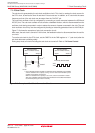
7.4.3 Stop Mode
In stop mode, all oscillator circuits are turned off, so are the CPU clock and the peripheral function clocks.
Therefore, the CPU and the peripheral functions clocked by these clocks stop operating. The least
amount of power is consumed in this mode. If the voltage applied to VCC is VRAM or more, the internal
RAM is retained.
However, the peripheral functions clocked by external signals keep operating. The following interrupts
can be used to exit stop mode.
______
• NMI interrupt
• Key interrupt
______
• INT interrupt
• Timer A, Timer B interrupt (when counting external pulses in event counter mode)
• Serial I/O interrupt (when external clock is selected)
• CAN0/1 Wake-up interrupt (when CAN sleep mode is selected)
7.4.3.1 Entering Stop Mode
The microcomputer is placed into stop mode by setting the CM10 bit in the CM1 register to “1” (all clocks
turned off). At the same time, the CM06 bit in the CM0 register is set to “1” (divide-by-8 mode) and the
CM15 bit in the CM1 register is set to “1” (main clock oscillator circuit drive capability high).
Before entering stop mode, set the CM20 bit in the CM2 register to “0” (oscillation stop, re-oscillation
detection function disabled).
Also, if the CM11 bit in the CM1 register is “1” (PLL clock for the CPU clock source), set the CM11 bit to
“0” (main clock for the CPU clock source) and the PLC07 bit in the PLC0 register to “0” (PLL turned off)
before entering stop mode.
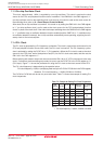
7.4.3.2 Pin Status in Stop Mode
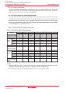
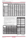
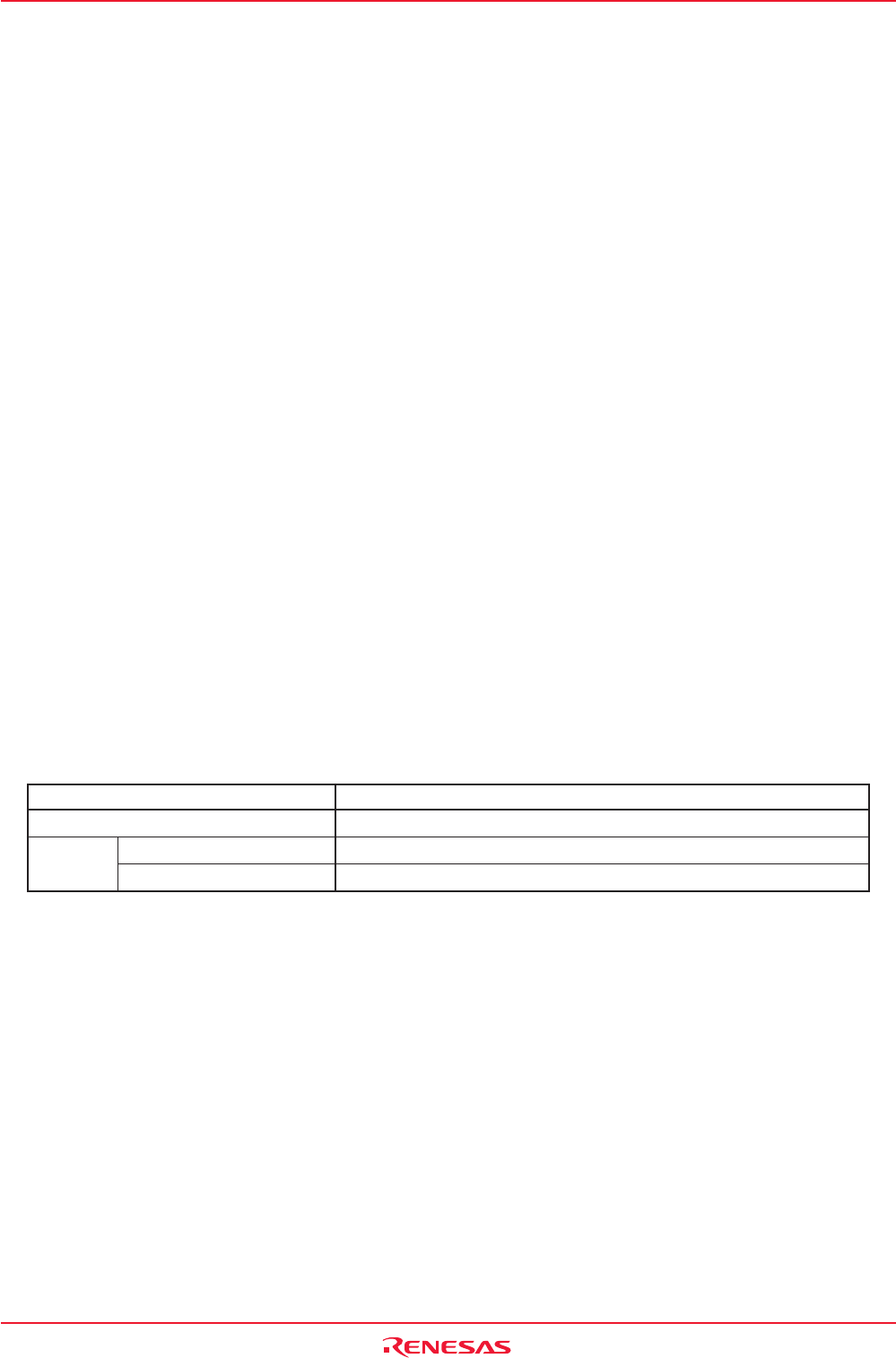
Table 7.6 lists the pin status in stop mode.
Table 7.6 Pin Status in Stop Mode
Pin Single-Chip Mode
I/O Ports Retains status before stop mode
CLKOUT “H”
Retains status before stop mode
When fC selected
When f8, f32 selected