


Rev.1.10 Jul 01, 2005 page 180 of 318
REJ09B0124-0110
M16C/6N Group (M16C/6NK, M16C/6NM) 14. Serial I/O
Under development
This document is under development and its contents are subject to change.
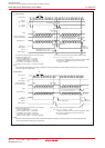
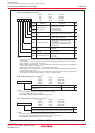
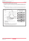
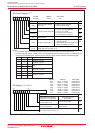
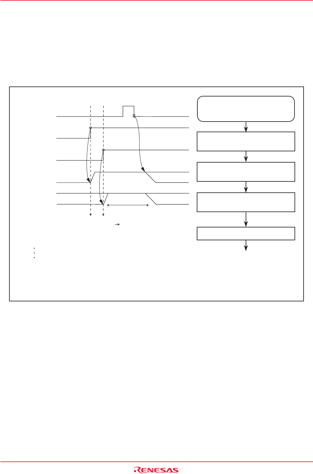
14.2.3 Functions for Setting an SOUTi Initial Value
If the SMi6 bit in the SiC register = 0 (external clock), the SOUTi pin output can be fixed high or low when
not transferring
(1)
. Figure 14.41 shows the timing chart for setting an SOUTi initial value and how to set it.
NOTE:
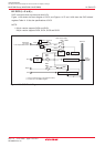
1. When CAN0 function is selected, P7_4, P7_5 and P8_0 can be used as input/output pins for SI/O4.
When CAN0 function is not selected, P9_5, P9_6 and P9_7 can be used as input/output pis for SI/O4.
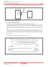
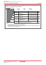
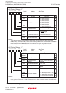
Figure 14.41 SOUTi’s Initial Value Setting
Setting the SOUTi
initial value to "H"
(2)
Port selection switching
(I/O port SOUTi)
D0
Initial value = H
(1)
Port output
D0
Signal written to
SiTRR register
SOUTi (internal)
SMi7 bit
SOUTi output
SMi3 bit
(Example) When "H" selected for SOUTi initial value
i = 3 to 6 (5 and 6 are only in the 128-pin version.)
* This diagram applies to the case where the bits in the SiC register are set as follows:
SMi2 = 0 (SOUTi output)
SMi5 = 0 (LSB first)
SMi6 = 0 (external clock)
NOTES:
1.If the SMi6 bit = 1 (internal clock) or if the SMi2 bit = 1 (SOUTi output disabled), this output
goes to the high-impedance state.
2.SOUTi can only be initialized when input on the CLKi pin is in the high state if the SMi4 bit in
the SiC register = 0 (transmit data output at the falling edge of the transfer clock) or in the low
state if the SMi4 bit = 1 (transmit data output at the rising edge of the transfer clock).
"H" level is output
from the SOUTi pin
Serial transmit/reception starts
Setting of the initial value of SOUTi
output and starting of
transmission/reception
Set the SMi3 bit to "1"
(SOUTi pin functions as SOUTi output)
Write to the SiTRR register
Set the SMi3 bit to "0"
(SOUTi pin functions as an I/O port)
Set the SMi7 bit to "1"
(SOUTi initial value = H)