


Rev.1.10 Jul 01, 2005 page 282 of 318
REJ09B0124-0110
M16C/6N Group (M16C/6NK, M16C/6NM) 22. Usage Precaution
Under development
This document is under development and its contents are subject to change.
22.4 Power Control
____________
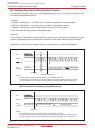
When exiting stop mode by hardware reset, set RESET pin to “L” until a main clock oscillation is stabilized.
Set the MR0 bit in the TAiMR register (i = 0 to 4) to “0” (pulse is not output) to use the timer A to exit stop
mode.
Insert more than four NOP instructions after an WAIT instruction or a instruction to set the CM10 bit in the
CM1 register to “1” (all clock stopped). When shifting to wait mode or stop mode, an instruction queue reads
ahead to the next instruction to halt a program by an WAIT instruction and an instruction to set the CM10 bit
to “1”. The next instruction may be executed before entering wait mode or stop mode, depending on a
combination of instruction and an execution timing.
In the main clock oscillation or low power dissipation mode, set the CM02 bit in the CM0 register to “0” (do
not stop peripheral function clock in wait mode) before shifting to stop mode.
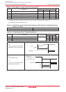
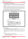
When entering wait mode by executing the WAIT instruction after writing to addresses 03FDh to 03FFh or
internal RAM area, execute the JMP.B instruction between writing to corresponding area and the executing
the WAIT instruction.
If DMA transfer may occur between executing the JMP.B instruction and the WAIT instruction, set the
DMAE bit (DMA enable bit) in the DMiCOM register (i = 0, 1) to “0” (disabled) before ececuting the WAIT
instruction.
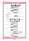
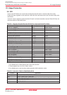
Example program MOV.B #55H, 0601H ; Write to internal RAM area
JMP.B L1
L1:
FSET I ; Enable interrupt
WAIT ; Enter to wait mode
When using the interrupt to exit stop mode, the fifth instruction
(1)
from the instruction to enter the stop mode
may be executed before executing a program of the interrupt to exit stop mode.
If this execution causes no problem with the system, there are no need for measures to be taken
(2)
.
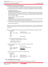
If such a situation presents a problem, execute the JMP.B instruction subsequent to the instruction which
sets the CM10 bit to “1” (stop mode).
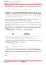
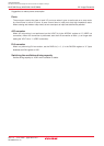
Example program BSET 0, CM1 ; Stop mode
JMP.B L1
L1:
Program after exiting stop mode
NOTES:
1. Insert more than four NOP instructions after the instruction shifting to wait mode or stop mode.
2. In the flash memory version, be sure to execute the measures. For details, refer to 22.18.2 Stop Mode.
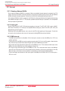
Wait for main clock oscillation stabilization time, before switching the clock source for CPU clock to the main
clock.
Similarly, wait until the sub clock oscillates stably before switching the clock source for CPU clock to the sub
clock.