


Rev.1.10 Jul 01, 2005 page 66 of 318
REJ09B0124-0110
M16C/6N Group (M16C/6NK, M16C/6NM) 9. Interrupt
Under development
This document is under development and its contents are subject to change.
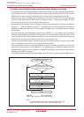
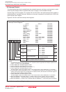
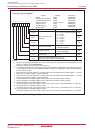
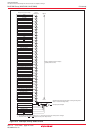
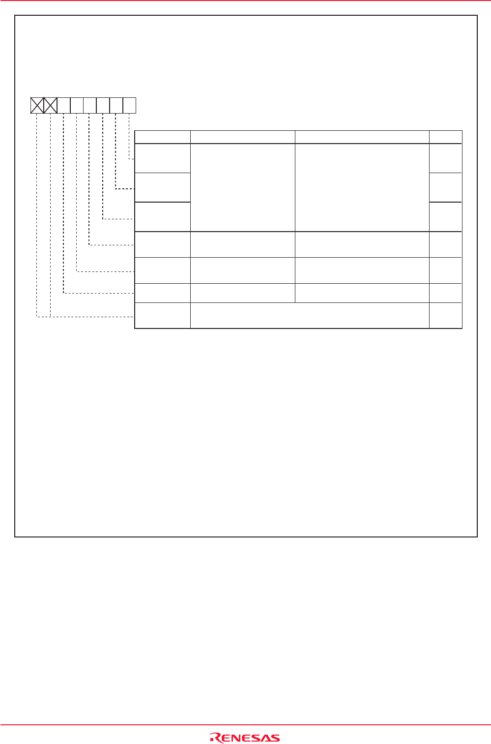
Figure 9.4 Interrupt Control Registers (2)
0044h
0048h
0049h
005Dh to 005Fh
0057h
0058h
005Bh
Interrupt Control Register
(1)
INT3IC
C1RECIC/S4IC/INT5IC
(6)
C1TRMIC/S3IC/INT4IC
(7)
INT0IC to INT2IC
TA2IC/INT7IC
(8)
TA3IC/INT6IC
(9)
TB1IC/INT8IC
(10)
XX00X000b
XX00X000b
XX00X000b
XX00X000b
XX00X000b
XX00X000b
XX00X000b
b2 b1 b0
0 0 0 : Level 0 (interrupt disabled)
0 0 1 : Level 1
0 1 0 : Level 2
0 1 1 : Level 3
1 0 0 : Level 4
1 0 1 : Level 5
1 1 0 : Level 6
1 1 1 : Level 7
0 : Interrupt not requested
1 : Interrupt requested
Nothing is assigned. When write, set to "0".
When read, their contents are indeterminate.
RW
RW
RW
RW
RW
(2)
-
Interrupt Request Bit
Interrupt Priority Level
Select Bit
Bit Name FunctionBit Symbol RW
Symbol Address After Reset
b7 b6 b5 b4 b3 b2 b1 b0
ILVL0
IR
0 : Selects falling edge
(3) (4) (5)
1 : Selects rising edge
ILVL1
ILVL2
-
(b7-b6)
Set to "0"
Polarity Select Bit
POL
Reserved Bit
-
(b5)
RW
0
NOTES:
1. To rewrite the interrupt control registers, do so at a point that does not generate the interrupt request for that
register. For details, refer to 22.7 Interrupt.
2. This bit can only be reset by writing "0" (Do not write "1").
3. If the IFSR10 to IFSR15 bits in the IFSR1 register and the IFSR23 to IFSR25 bits in the IFSR2 register are
"1" (both edges), set the POL bit in the INT0IC to INT8IC register to "0" (falling edge). INT6IC to INT8IC registers
are in the 128-pin version.
4. Set the POL bit in the S3IC register to "0" (falling edge) when the IFSR00 bit in the IFSR0 register = 1 and the
IFSR16 bit in the IFSR1 register = 0 (SI/O3 selected).
5. Set the POL bit in the S4IC register to "0" (falling edge) when the IFSR03 bit in the IFSR0 register = 1 and the
IFSR17 bit in the IFSR1 register = 0 (SI/O4 selected).
6. Use the IFSR03 bit in the IFSR0 register and the IFSR17 bit in the IFSR1 register to select.
7. Use the IFSR00 bit in the IFSR0 register and the IFSR16 bit in the IFSR1 register to select.
8. Use the IFSR20 bit in the IFSR2 register to select.
The INT7IC register is only in the 128-pin version. In the 100-pin version, set the IFSR20 bit to "0" (Timer A2).
9. Use the IFSR21 bit in the IFSR2 register to select.
The INT6IC register is only in the 128-pin version. In the 100-pin version, set the IFSR21 bit to "0" (Timer A3).
10. Use the IFSR22 bit in the IFSR2 register to select.
The INT8IC register is only in the 128-pin version. In the 100-pin version, set the IFSR22 bit to "0" (Timer B1).