


Rev.1.10 Jul 01, 2005 page 35 of 318
REJ09B0124-0110
M16C/6N Group (M16C/6NK, M16C/6NM) 7. Clock Generating Circuit
Under development
This document is under development and its contents are subject to change.
7. Clock Generating Circuit
7.1 Types of Clock Generating Circuit
Four circuits are incorporated to generate the system clock signal:
• Main clock oscillation circuit
• Sub clock oscillation circuit
• On-chip oscillator
• PLL frequency synthesizer
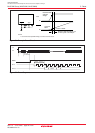
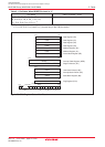
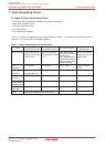
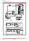
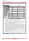
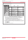
Table 7.1 lists the clock generating circuit specifications. Figure 7.1 shows the clock generating circuit.
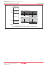
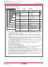
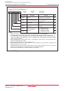
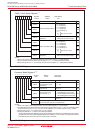
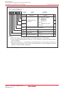
Figures 7.2 to 7.8 show the clock-related registers.
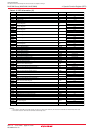
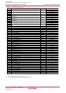
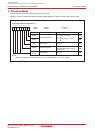
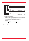
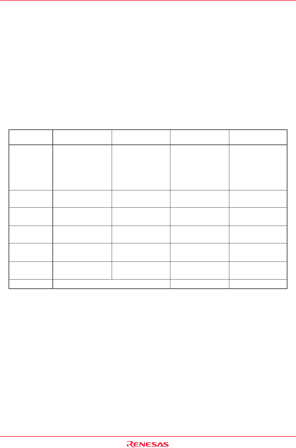
Table 7.1 Clock Generating Circuit Specifications
Item
Main Clock
Oscillation Circuit
Sub Clock
Oscillation Circuit
On-chip Oscillator
PLL Frequency
Synthesizer
Use of Clock
Clock
Frequency
Usable
Oscillator
Pins to Connect
Oscillator
Oscillation Stop
and Re-Oscillation
Detection Function
Oscillation Status
After Reset
Other
• CPU clock source
• Peripheral function
clock source
0 to 16 MHz
•Ceramic oscillator
•Crystal oscillator
XIN, XOUT
Available
Oscillating
Externally derived clock can be input
• CPU clock source
• Clock source of Timer
A, B
32.768 kHz
•Crystal oscillator
XCIN, XCOUT
Available
Stopped
• CPU clock source
• Peripheral function
clock source
• CPU and peripheral
function clock sources
when the main clock
stops oscillating
About 1 MHz
-
-
Available
Stopped
-
• CPU clock source
• Peripheral function
clock source
16 MHz, 20 MHz,
24 MHz
-
-
Available
Stopped
-