


Rev.1.10 Jul 01, 2005 page 119 of 318
REJ09B0124-0110
M16C/6N Group (M16C/6NK, M16C/6NM) 13. Three-Phase Motor Control Timer Function
Under development
This document is under development and its contents are subject to change.
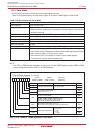
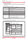
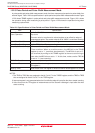
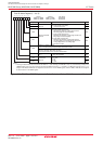
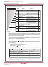
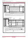
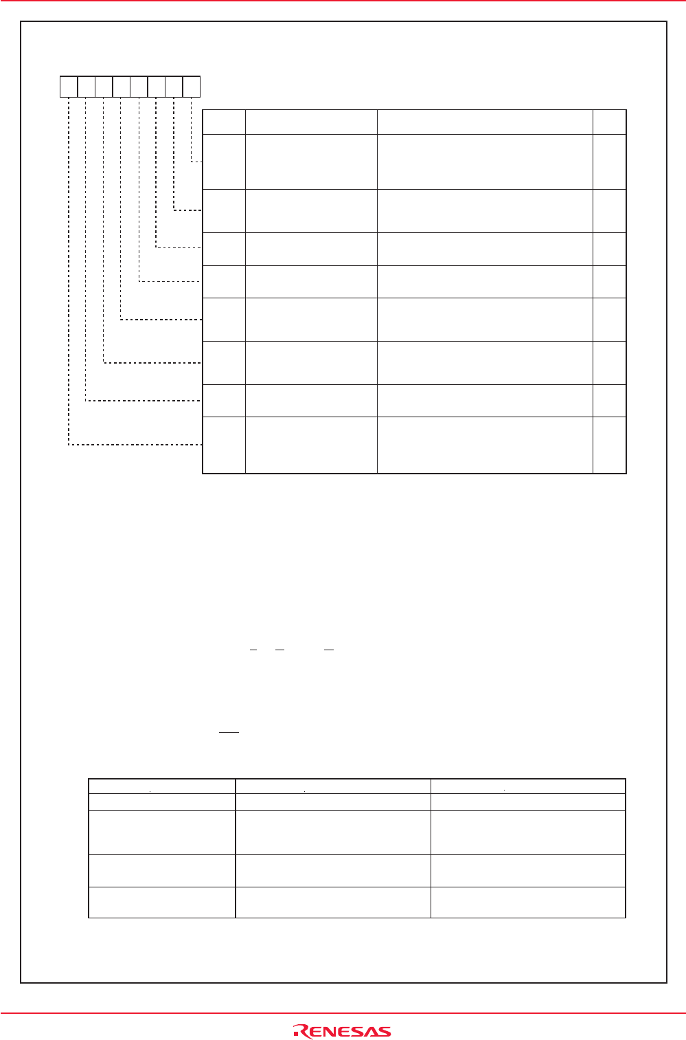
Figure 13.2 INVC0 Register
NOTES:
1. Set the INVC0 register after the PRC1 bit in the PRCR register is set to "1" (write enable).
Rewrite the INV00 to INV02 and INV06 bits when the timers A1, A2, A4 and B2 stop.
2. The INV00 and INV01 bits are enabled only when the INV11 bit is set to "1" (three-phase mode 1). The ICTB2
counter is incremented by one every time the timer B2 underflows, regardless of INV00 and INV01 bit settings,
when the INV11 bit is set to "0" (three-phase mode 0).
When setting the INV01 bit to "1", set the timer A1 count start flag before the first timer B2 underflow.
When the INV00 bit is set to "1", the first interrupt is generated when the timer B2 underflows
n-1
times, if
n
is
the value set in the ICTB2 counter. Subsequent interrupts are generated every
n
times the timer B2 underflows.
3. Set the INV01 bit to "1" after setting the ICTB2 register .
4. Set the INV02 bit to "1" to operate the dead time timer, U-, V-and W-phase output control circuits and ICTB2
counter.
5. When the INV02 bit is set to "1" (three-phase control timer functions) and the INV03 bit to "0" (three-phase
control timer output disabled), U, U, V, V, W and W pins, including pins shared with other output functions, enter
a high-impedance state.
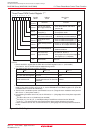
6. The INV03 bit is set to "0" when the followings occurs :
- Reset
- A concurrent active state occurs while INV04 bit is set to "1"
- The INV03 bit is set to "0" by program
- A signal applied to the NMI pin changes "H" to "L"
7. The INV05 bit cannot be set to "1" by program. Set the INV04 bit to "0", as well, when setting the INV05 bit to "0".
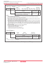
8. The following table describes how the INV06 bit works.
INV00
INV01
INV02
INV03
INV05
INV06
INV07
INV04
Function
Three-Phase PWM Control Register 0
(1)
Bit Name
Bit
Symbol
Symbol Address After Reset
INVC0 01C8h 00h
RW
RW
RW
RW
RW
RW
RW
RW
RW
Item
INV06 = 0
INV06 =
1
Transfer trigger is generated when the INV07
bit is set to "1". Trigger to the dead time timer
is also generated when setting the INV06
bit to "1". Its value is "0" when read.
Transfer trigger : Timer B2 underflows and write to the INV07 bit, or write to the TB2 register when INV10 = 1
0: The ICTB2 counter is incremented by one on the
rising edge of the timer A1 reload control signal
1: The ICTB2 counter is incremented by one on the
falling edge of the timer A1 reload control signal
(
2)
0: ICTB2 counter is incremented by one when
timer B2 underflows
1: Selected by the INV00 bit
(2)
9. When the INV06 bit is set to "1", set the INV11 bit to "0" (three-phase mode 0) and the PWCON bit in the TB2SC
register to "0" (reload timer B2 with timer B2 underflow).
Transferred once by generating a
transfer trigger after setting the IDB0
and IDB1 registers
Interrupt Enable Output
Polarity Select Bit
Interrupt Enable Output
Specification Bit
(3)
Mode Select Bit
(4)
0: No three-phase control timer functions
1: Three-phase control timer function
(5)
0:
Disables three-phase control timer output
(5)
1:
Enables three-phase control timer output
(6)
Output Control Bit
0: Enables concurrent active output
1: Disables concurrent active output
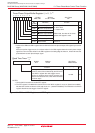
Positive and Negative-
Phases Concurrent Active
Disable Function Enable Bit
Positive and Negative-
Phases Concurrent Active
Output Detect Flag
0: Not detected
1: Detected
(7)
Modulation Mode
Select
(8)
0: Triangular wave modulation mode
1: Sawtooth wave modulation mode
(9)
Software Trigger Select
Bit
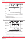
Transferred every time a transfer trigger
is generated
By a transfer trigger, or the falling edge of
a one-shot pulse of the timer A1, A2 or A4
On the falling edge of a one-shot pulse
of the timer A1, A2 or A4
Timing to Trigger the Dead Time
Timer when the INV16 Bit=0
INV13 Bit
Enabled when the INV11 bit=1 and the
INV06 bit=0
Disabled
Timing to Transfer from the IDB0
and IDB1 Registers to Three-
Phase Output Shift Register
Mode
Triangular wave modulation mode
Sawtooth wave modulation mode
b7 b6 b5 b4 b3 b2 b1 b0