


Rev.1.10 Jul 01, 2005 page 95 of 318
REJ09B0124-0110
M16C/6N Group (M16C/6NK, M16C/6NM) 12. Timers
Under development
This document is under development and its contents are subject to change.
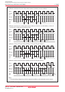
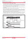
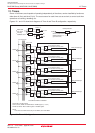
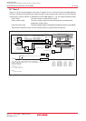
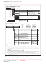
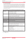
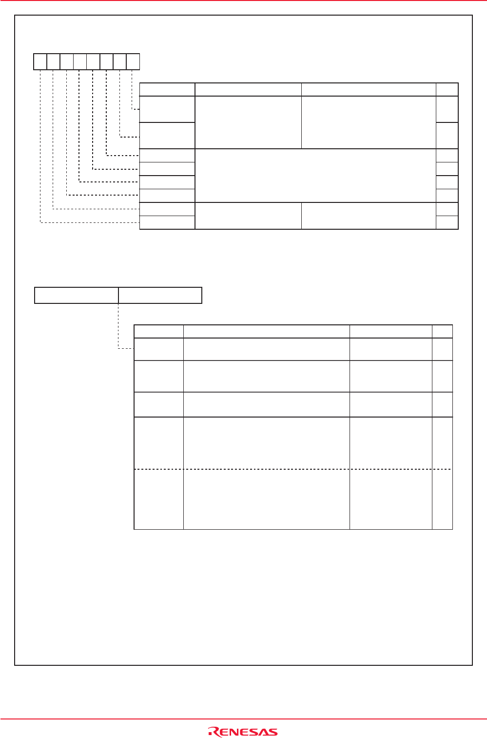
Figure 12.4 TA0MR to TA4MR Registers and TA0 to TA4 Registers
Timer Ai Mode Register (i = 0 to 4)
TA0MR to TA4MR
Bit Name FunctionBit Symbol
RW
b7 b6 b5 b4 b3 b2 b1 b0
0 0 : Timer mode
0 1 : Event counter mode
1 0 : One-shot timer mode
1 1 : Pulse width modulation mode
b1 b0
Count Source Select Bit
RW
RW
RW
RW
RW
RW
RW
RW
Function varies with each
operation mode
Symbol
Function varies with each operation mode
Operation Mode Select Bit
TCK1
MR3
MR2
MR1
TMOD1
MR0
TMOD0
TCK0
0396h to 039Ah 00h
Address After Reset
Symbol Address After Reset
TA0 0387h to 0386h
0389h to 0388h
038Bh to 038Ah
038Dh to 038Ch
038Fh to 038Eh
Indeterminate
TA1 Indeterminate
TA2 Indeterminate
TA3 Indeterminate
TA4
b7 b0b7 b0
(b15) (b8)
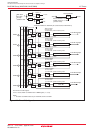
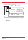
Timer Ai Register (i = 0 to 4)
(1)
RW
Divide the count source by n + 1 where n =
set value
Function Setting Range
Divide the count source by n where n = set
value and cause the timer to stop
Modify the pulse width as follows:
PWM period: (2
16
—
1) / fj
High level PWM pulse width: n / fj
where n = set value, fj = count source
frequency
NOTES:
1.The register must be accessed in 16-bit unit.
2.The timer counts pulses from an external device or overflows or underflows in other timers.
3.If the TAi register is set to "0000h", the counter does not work and timer Ai interrupt requests are
not generated either. Furthermore, if "pulse output" is selected, no pulses are output from the
TAiOUT pin.
4.Use the MOV instruction to write to the TAi register.
5.If the TAi register is set to "0000h", the pulse width modulator does not work, the output level on
the TAiOUT pin remains low, and timer Ai interrupt requests are not generated either.
The same applies when the 8 high-order bits in the TAi register are set to "00h" while operating as
an 8-bit pulse width modulator.
RW
RW
WO
WO
WO
Timer
Mode
Event
Counter
Mode
One-shot
Timer Mode
Pulse Width
Modulation
Mode
(16-bit PWM)
Pulse Width
Modulation
Mode
(8-bit PWM)
0000h to FFFFh
0000h to FFFFh
00h to FEh
(High-order address)
00h to FFh
(Low-order address)
0000h to FFFFh
(3) (4)
0000h to FFFEh
(4) (5)
Mode
Modify the pulse width as follows:
PWM period: (2
8
—
1) ✕ (m + 1)/ fj
High level PWM pulse width: (m + 1)n / fj
where n = high-order address set value,
m = low-order address set value, fj =
count source frequency
Divide the count source by FFFFh
—
n + 1
where n = set value when counting up or
by n + 1 when counting down
(2)
Indeterminate