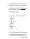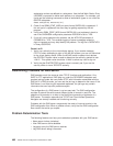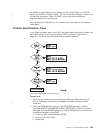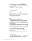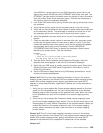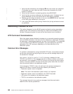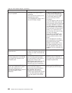
Table 46. LPD Problem Analysis (continued)
Problem Cause Solution
Notes:
1. The QPTMPLPD printer file should be set to *USERASCII because LPD expects to receive ASCII data from
non-AS/400 systems. The *USERASCII device type on the printer file does not mean that the data stream of the
spooled file is ASCII. If, for example, AFPDS data is sent from a non-AS/400 system, the data is sent as
*USERASCII and will not print correctly.
2. The sending system does not know that the file was not spooled because LPD does not search for a place to
store the file until after it has received all the data from the sending system.
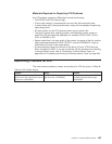
Materials Required for Reporting LPD Problems
Any LPD problem reported to IBM should include the following:
v Any problems that cause LPD to fail unexpectedly will generate spooled files as
part of the LPD error handling. Three spooled files are created inside the failing
job from these commands:
QSYS/DSPJOBLOG JOB(*) OUTPUT(*PRINT)
QSYS/DSPJOB OUTPUT(*PRINT)
QSYS/DMPOBJ OBJ(QUSRSYS/QTMPLPD8MM)
OBJTYPE(*USRQ)
These 3 files will be owned by either the sending user profile, the default user
profile QTMPLPD or the QTCP user profile.
v The QTCPIP and LPD client job logs.
v If file or data integrity is compromised, then any files that are being sent.
v If the file being sent is being transformed, a copy of the workstation customizing
object being used.
v If the file being received is an AS/400 spooled file sent with TRANSFORM=*YES,
or is coming from a non-AS/400 client, include the description of the
QUSRSYS/QPTMPLPD printer file.
v The type of remote host, operating system, and operating system version from
which the LPR command was attempted, for example, PS/2 to OS/2, PS/2 to
DOS, or RS/6000 to AIX.
v A communications trace from the time of the failure (format TCP/IP data only),
formatted for both ASCII and EBCDIC. If you are not familiar with the procedure
for collecting a communications trace, refer to “Collecting a Communications
Trace” on page 493 and “Formatting and Saving the Communications Trace” on
page 499.
Determining Problems with REXEC
If a problem is detected when using the REXEC server, use the following flow chart
to identify the cause after using the flow chart for general TCP/IP problems
(Figure 247 on page 431). The cause lists that follow identify potential problems.
Chapter 21. TCP/IP Problem Analysis 489


